
System and method for forming of tubular parts

a technology of tubular parts and forming systems, applied in forging presses, forging/pressing/hammering apparatuses, manufacturing tools, etc., can solve the problems of insufficient dimensional repeatability, lack of concentricity, and inability to predict the thickness of the wall in the die corner, so as to achieve effective forming of hollow parts, high energy rate deformation, and high tensile strength

Inactive Publication Date: 2011-04-21
NEW JERSEY INSTITUTE OF TECHNOLOGY
View PDF9 Cites 5 Cited by
  • Summary
  • Abstract
  • Description
  • Claims
  • Application Information

AI Technical Summary

Benefits of technology

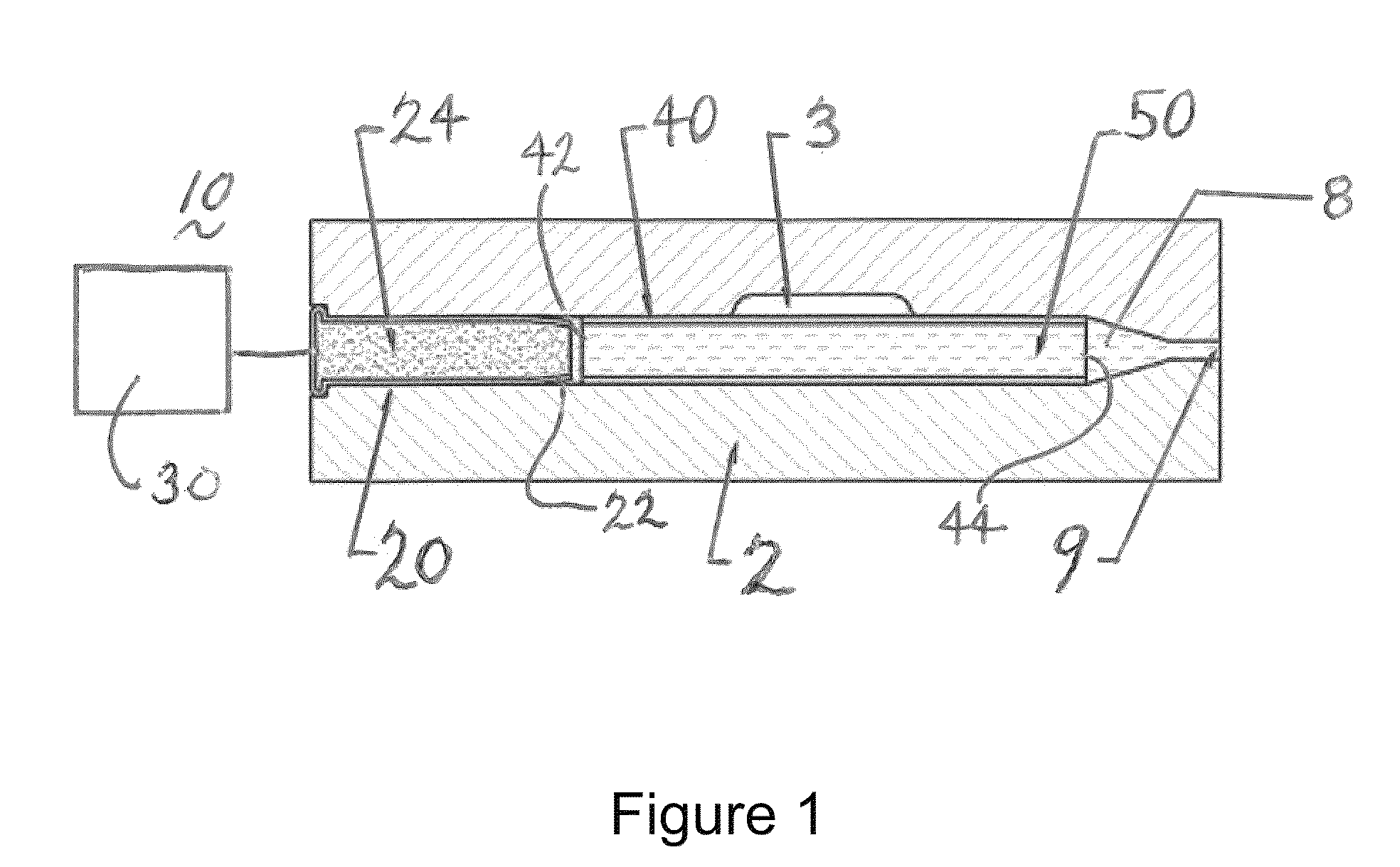
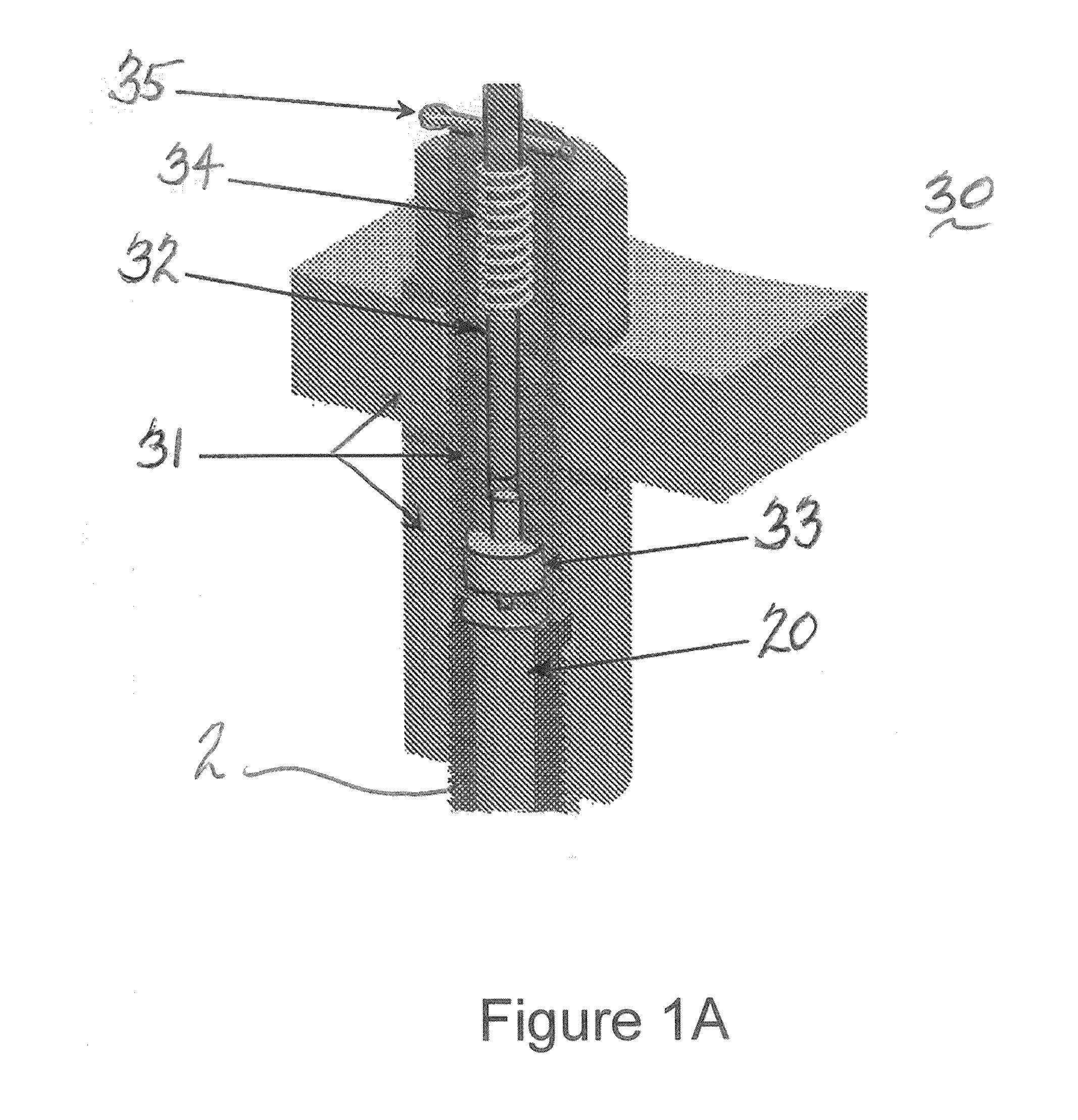
The present invention relates to a method and apparatus for forming high-strength materials using a propellant-driven water stream. The process involves using a die and a combustion chamber to mold the material in the desired shape. The high pressure generated by the combustion of the propellant charges the water stream with force, resulting in the formation of the material in the desired shape. The apparatus includes a die, a combustion chamber, a nozzle, and an ignition mechanism. The method and apparatus can be used to form tubular components with high strength and integrity.

Problems solved by technology

However, in many cases the geometry and material choice of hollow parts are determined by the cost of fabrication rather than design optimization.
The drawbacks of the hydroforming process include unpredictable wall thinning in die corners, insufficient dimensional repeatability, lack of concentricity, and work hardening.
These features impede process applications for forming repeatable, precise, and structurally sound expanded components.
Another significant obstacle preventing wide adoption of a hydrostatic expansion technique is the high capital cost of forming equipment (pumps, presses, etc.).
The main disadvantage of explosive forming is the lack of ability to produce small, precise, or large manufacturing volume parts.

Method used


Image

  • System and method for forming of tubular parts
  • System and method for forming of tubular parts
  • System and method for forming of tubular parts

Examples


example

[0069]Now referring to FIGS. 12 and 12A, a compressor high pressure stage bleed tube for commercial applications was formed in accordance with the present disclosures. The bleed tube was made from OD 0.500×0.028 thick AMS 4943 tube.

[0070]As was shown above, multiple exemplary embodiments of the present invention show the traveling compression waves propagate with the speed of sound through a liquid stream flowing through a work piece confined by a die. Due to the nature of the traveling waves at each instant of time, only a section of a work piece and a die are exposed to the high water pressure. Thus while super-high pressure is exerted on the die halves, the total force separating them is rather limited. This significantly simplifies, and in fact makes practical, the design of tools for the implementation of the proposed forming technology described herein.


PUM

PropertyMeasurementUnit
pressureaaaaaaaaaa
melting temperatureaaaaaaaaaa
Brinell hardnessaaaaaaaaaa

Abstract

Apparatus and methods are disclosed whereby a propellant driven water stream is used in the formation of materials made from high tensile strength alloys. High pressure developed in liquid flowing through a tubular work piece is employed to achieve desired forms. The high pressure results from superposition of compression waves generated in the course of the impact of the liquid by products of propellant combustion.

Description

CROSS-REFERENCE TO RELATED APPLICATIONS[0001]This application claims the benefit of U.S. Provisional Patent Application No. 61 / 251,997 filed Oct. 15, 2009 and U.S. Provisional Patent Application No. 61 / 298,662 filed Jan. 27, 2010, the entireties of which are incorporated herein by reference.FIELD OF THE INVENTION[0002]The present invention relates to the use of a liquid, such as water, as a medium for conversion of available chemical, mechanical or electrical energy into kinetic energy. In particular the present invention relates to apparatus for, and methods of, forming materials of high tensile strength such as alloys using propellant driven water streams.BACKGROUND OF THE INVENTION[0003]Almost any mechanical device contains hollow shapes, such as tubes, shafts, shells, housings and the like. Such features as the ability to contain and guide liquid streams, minimal weight-to-strength ratio, etc. make these parts indispensable in the design of practically any mechanical device or s...

Claims


Application Information

Patent Timeline
Patent Type & Authority Applications(United States)
IPC IPC(8): F16L9/00B21D26/033
CPCB21D26/08Y10T29/49806Y10S72/706F16L9/22
Inventor GESKIN, ERNEST SAMUELKLUZ, KRZYSZTOF
Owner NEW JERSEY INSTITUTE OF TECHNOLOGY
Learn More