Battery device and method of packaging, disassembling, and recycling thereof

a battery device and battery technology, applied in the direction of secondary cell servicing/maintenance, cell components, cell component details, etc., can solve the problems of general inability to provide stable power generation, bottleneck of alternative sources, low energy conversion efficiency, etc., to improve the stability of the whole battery device structure.

Inactive Publication Date: 2010-12-09
ADVANCED POWER & ENERGY SOURCES HK
View PDF7 Cites 14 Cited by
  • Summary
  • Abstract
  • Description
  • Claims
  • Application Information

AI Technical Summary

Benefits of technology

[0014]Furthermore, in order to improve the stability of the whole battery device structure, the battery device packaging step further includes (4) using at least one buckling member to buckle and fasten the metallic fastener.

Problems solved by technology

However, fossil fuels and nuclear power have serious environmental problems and low energy-conversion efficiency, making alternative energy increasingly attractive.
But the great bottleneck for alternative sources is their general inability to provide stable power generation.
However, it is not feasible to rapidly disassemble such a battery and to recycle its internal materials at the end of its life with the conventional designs.
And the packaging mechanism of a fuel cell is getting more complex to provide better packaging, particularly for safety.
This not only increases the size of a fuel cell but also complicates the structure so that it is more difficult to disassemble or recycle such a fuel cell.
The situation gets worse when multiple cells are connected in series or parallel together with a fuel tank to form a hybrid power mechanism.
Moreover, when a fuel cell runs out of fuel, it is typically necessary to send the cell back to the manufacturer or to a maintenance company for recycling, and the cell will need to undergo a series of complex processes in order to be disassembled and repackaged.
This further increases the costs in terms of labor and equipment.

Method used


Image

  • Battery device and method of packaging, disassembling, and recycling thereof
  • Battery device and method of packaging, disassembling, and recycling thereof
  • Battery device and method of packaging, disassembling, and recycling thereof

Examples


Embodiment Construction

[0031]Specific embodiments are herein described in detail to explain the present invention, wherein numerous advantages and effects will be readily apparent to those skilled in the art once the disclosure is fully appreciated. It should be noted that the present invention may be implemented with various embodiments. According to different aspects and applications, the details of this specification may be altered or modified without departing from the spirit of the present invention.

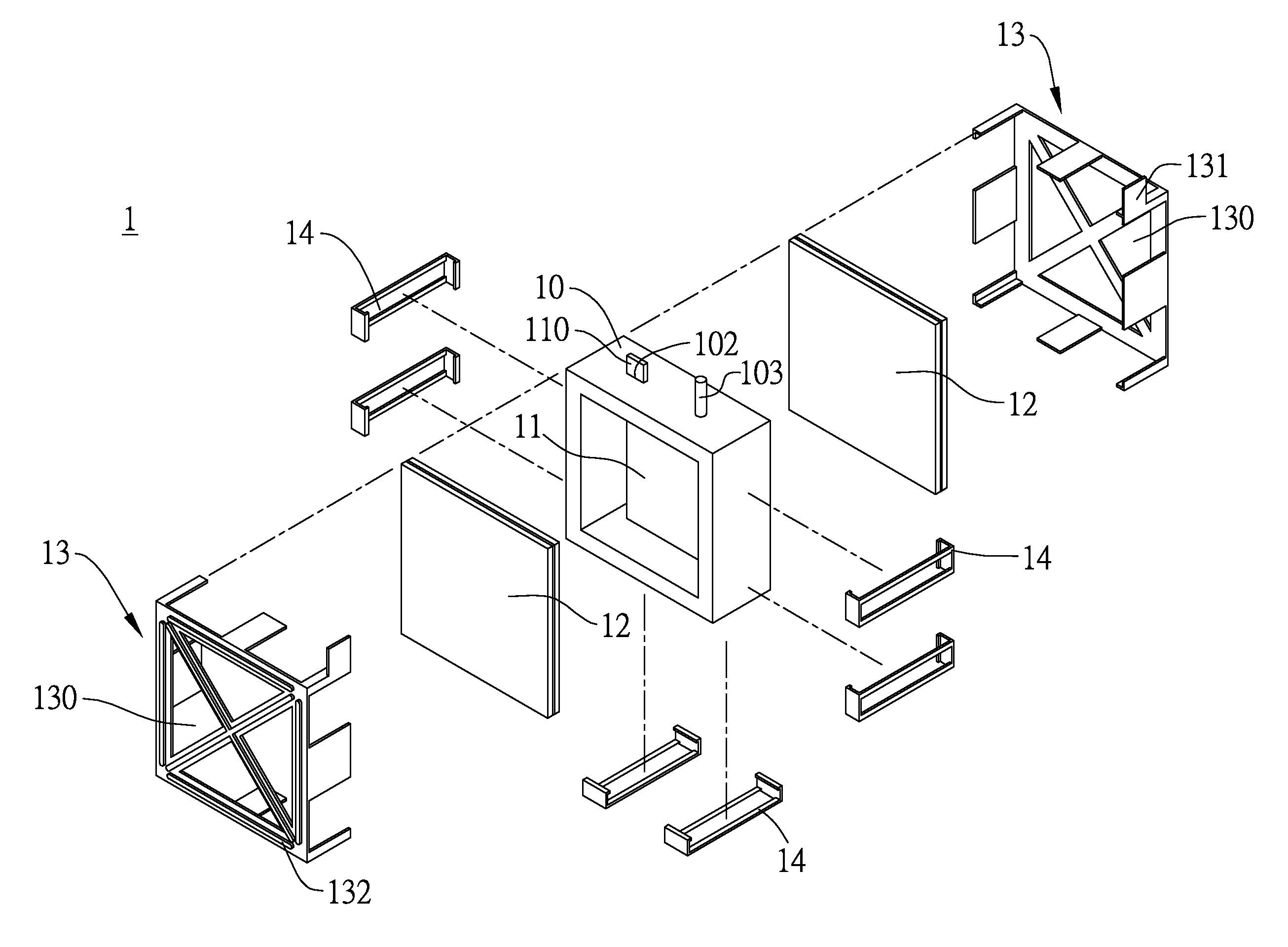
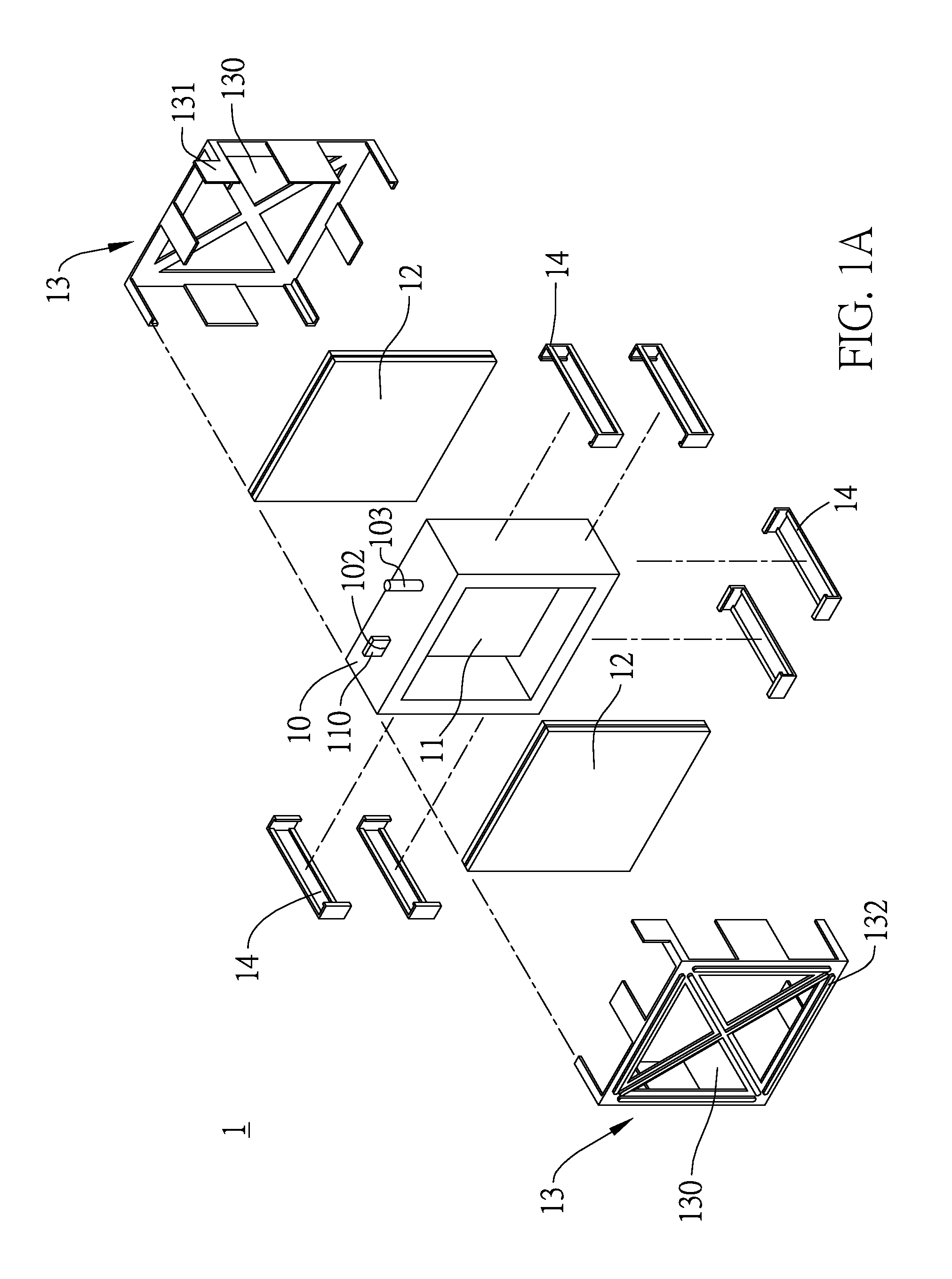
[0032]FIG. 1A provides an exploded view of the battery device according to the present invention. As shown in FIG. 1A, the battery device 1 includes: a reaction trough frame 10, an anode conductive element 11, two sets of cathode conductive elements 12, a metallic fastener 13, and buckling member 14.

[0033]The reaction trough frame 10 is made of plastic, artificial or natural rubber, ethylene propylene diene methylene (EPDM), and so on. It has a first opening 100 (see FIG. 1D), second opening 101 (see FIG....


PUM

PropertyMeasurementUnit
thicknessaaaaaaaaaa
conductiveaaaaaaaaaa
metallicaaaaaaaaaa

Abstract

The invention provides a battery device and a method for packaging, disassembling, and recycling the battery device, wherein the anode conductive element is disposed in a reaction trough frame with a bump thereof protruding from the frame; two sets of the cathode conductive elements cover on a first opening and a second opening of the reaction trough frame, respectively, so as to form a reaction region for accommodating electrolyte therein; and a metallic fastener is disposed on surfaces of the cathode conductive elements and the reaction trough frame and fastened with a buckling member. The invention provides a simple structure that can be packaged rapidly, disassembled and recycled to thereby overcome the drawbacks of conventional batteries.

Description

BACKGROUND OF THE INVENTION[0001]1. Field of the Invention[0002]The present invention relates to a battery device and a method of packaging, disassembling and recycling the battery device, and, more specifically, to a battery device capable of being rapidly packaged, disassembled and recycled.[0003]2. Description of Related Art[0004]With regard to power sources, despite the emergence of solar, wind, tidal and geothermal alternatives, modern society still relies on stable power sources like fossil fuels (coal, oil and gas) or nuclear power. However, fossil fuels and nuclear power have serious environmental problems and low energy-conversion efficiency, making alternative energy increasingly attractive. But the great bottleneck for alternative sources is their general inability to provide stable power generation. Hence the fuel cell, which converts chemical energy into electricity, has been proposed as a solution that would provide both good stability and efficiency.[0005]A fuel cell ...

Claims


Application Information

Patent Timeline
Patent Type & Authority Applications(United States)
IPC IPC(8): H01M2/02H01M8/04H01M10/42
CPCH01M8/008H01M8/0206H01M8/0273H01M8/08Y10T29/49108H01M8/248H01M8/249Y02E60/50H01M8/2475Y02W30/84
Inventor HUANG, HSUEH CHENGCHANG, KENG-RONGLEE, GUO-LINCHIU, WAN CHINGLI, FU-SHENG
Owner ADVANCED POWER & ENERGY SOURCES HK
Why Eureka
Try Eureka