Angled reaction vessel

Inactive Publication Date: 2010-10-14
BIOMASS WORLDWIDE GROUP +1
View PDF102 Cites 30 Cited by
  • Summary
  • Abstract
  • Description
  • Claims
  • Application Information

AI Technical Summary

Benefits of technology

[0013]The reaction vessel and processes described herein result in the highly efficient and safe separation of the cellulosic fraction from a biomass waste stream. Efficiency is conferred by improvements which result in the use of less process steam to treat the biomass bearing material which thereby: 1) reduces the quantity of vented end-of-process steam and therefore condensate; 2) improves the isolation of recyclable materials by reducing surface tension promoted by excess moisture; 3) extends the shelf life of processed biomass by reducing the moisture content; 4) extends and improves the operational life of the vessel by stabilizing operating conditions; 5) reduces or eliminates the need for post treatment processing, e.g., drying, of the materials for other uses; and 6) reduces contamination of the cellulosic fraction with plastic material and other containments because of the reduced temperatures and pressures. As discussed in greater detail below, improved safety results from the improved door, door sealing system, and insulated heated jacket that each reduce the risk of an operator being injured during use of the vessel.
[0043]Because of an increased surface area and homogenous sizing caused by the novel process, the feedstock may be efficiently used for use in gasification. The produced gas can be utilized as a substitute for natural gas or can be compressed or liquefied. The produced gas, or “syngas”, could also be stripped of various elements, including hydrogen. The syngas can also be converted by other methods into ethanol, “bio oils” and other chemicals or energy sources. Alternatively, the feedstock can be used in the process of hydrolysis, whereby the feedstock is used to produce sugars for distillation and other uses. The feedstock can also serve in a solid energy product, in which free flowing solids or pelletized or granular feed are burned for energy

Problems solved by technology

Handling solid waste is an increasingly difficult problem.
However, nationwide the availability of solid waste landfills is decreasing as landfills reach capacity and close, while opening new landfills is difficult due to regulations.
Some experts contend that there is no waste volume problem, but there exists a sorting and recycling problem.
Due to the remaining plastic contaminants in solid waste and refuse derived fuels, these incinerators are also highly regulated and expensive to maintain.
However, high quality cellulosic material that has very low contamination from plastic materials may be certified as a renewable organic based fuel that is not as highly regulated.
These reaction vessels have eccentricities in the axis of rotation that are introduced during the manufacture and installation of the vessel or are caused by eccentric or other expansion of the metal vessel during operation.
The eccentricities can result in the centerline of the vessel moving a significant distance during rotation of the vessel.
These asymmetric changes can decrease the operating efficiency of the vessel by increasing the difficulty of forming an effective seal between the vessel and the door.
Moreover, the eccentric movement of the vessel can increase operating costs of the vessel due to stresses that can be transferred to door supporting structures during operation.
Many prior reaction vessels for treating biomass bearing material utilize inefficient high-pressure steam systems to cook and soften the cellulosic fibers of the biomass bearing material.
High-pressure steam vessels are undesirable because 1) they require significant licensing and inspection regimes; 2) they must be built to withstand higher pressure which greatly increases their cost; 3) they require a great amount of energy to generate and maintain the high operating pressures, which results in high operating costs; 4) cycling between the high operating pressures and the emptying pressure results in the inefficient loss of a large amount of energy; 5) high operating pressures present significant safety concerns; and 6) high pressure, high pressure steam results in contamination of the cellulosic fraction such as by melted plastic materials that decreases the quality of the fraction and limits its use as a feedstock for various processes.

Method used


Image

  • Angled reaction vessel
  • Angled reaction vessel
  • Angled reaction vessel

Examples


Embodiment Construction

[0070]While the invention is susceptible of various modifications and alternative constructions, certain illustrated embodiments thereof have been shown in the drawings and will be described below in detail. It should be understood, however, that there is no intention to limit the invention to the specific form disclosed, but, on the contrary, the invention is to cover all modifications, alternative constructions, and equivalents falling within the spirit and scope of the invention as defined in the claims.

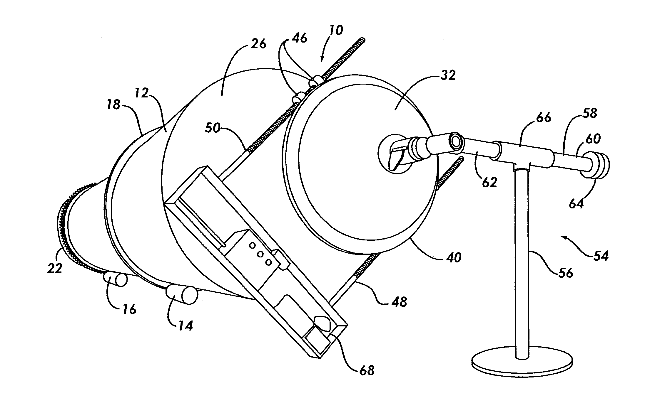
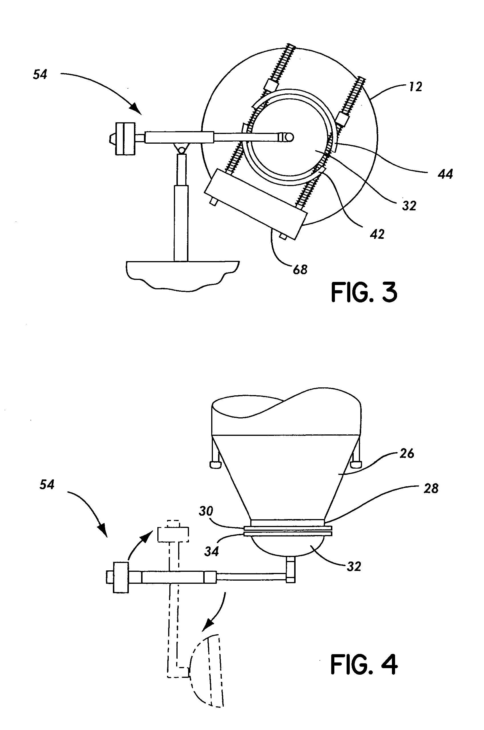
[0071]Some of the preferred embodiments are shown in the FIGS. 1 through 24. FIG. 1 shows the biomass bearing material treatment vessel 10. It includes a reaction vessel 12. In one mode of the invention, a first trunnion assembly 14 and a second trunnion assembly 16 supports the reaction vessel 12. The trunnion assembly includes a track 18 and a trunnion 20. These components can be sized according to the size of a specific reaction vessel. However, in a preferred embodiment of the...


PUM

PropertyMeasurementUnit
Pressureaaaaaaaaaa
Angleaaaaaaaaaa
Perimeteraaaaaaaaaa

Abstract

An improved apparatus and process for treating biomass bearing material including municipal solid waste (MSW). The apparatus includes a reaction vessel configured for rotation and steam injection, with helically arranged auger vanes attached to the internal walls of the vessel, a self aligning door. Embodiments includes various of a heated jacket, modified raised projections on the top edge of the auger vanes, a modified door, modified door sealing assembly, and a process of quick charging the interior of the vessel with steam.

Description

RELATED APPLICATION[0001]This application claims the benefit of U.S. application Ser. No. 11 / 355,632 filed on Feb. 16, 2006 (and having Publication No. 2007 / 01990643), the disclosure of which is expressly incorporated by reference herein in its entirety. Said application will issue as U.S. Pat. No. 7,745,208 on Jun. 29, 2010.FIELD OF THE INVENTION[0002]The present invention generally relates to processing biomass bearing material including municipal solid waste (MSW), and more particularly relates to reaction vessels for treating biomass bearing material and other material containing cellulose or biomass in a heated and pressurized process.BACKGROUND OF THE INVENTION[0003]Handling solid waste is an increasingly difficult problem. A majority of the United States' solid waste is disposed of in landfills. However, nationwide the availability of solid waste landfills is decreasing as landfills reach capacity and close, while opening new landfills is difficult due to regulations. The nat...

Claims


Application Information

Patent Timeline
IPC IPC(8): C07H1/06B01J19/28
CPCB09B3/00B09B3/0091C10L3/08C12M27/10C12M21/00C12M21/04C12M23/06Y02E50/343Y02E50/30B09B3/45
Inventor NOLL, ANTHONY P.HICKS, SCOTT F.
Owner BIOMASS WORLDWIDE GROUP
Why Eureka
Try Eureka