Control apparatus of alternating-current motor
- Summary
- Abstract
- Description
- Claims
- Application Information
AI Technical Summary
Benefits of technology
Problems solved by technology
Method used
Image
Examples
first embodiment
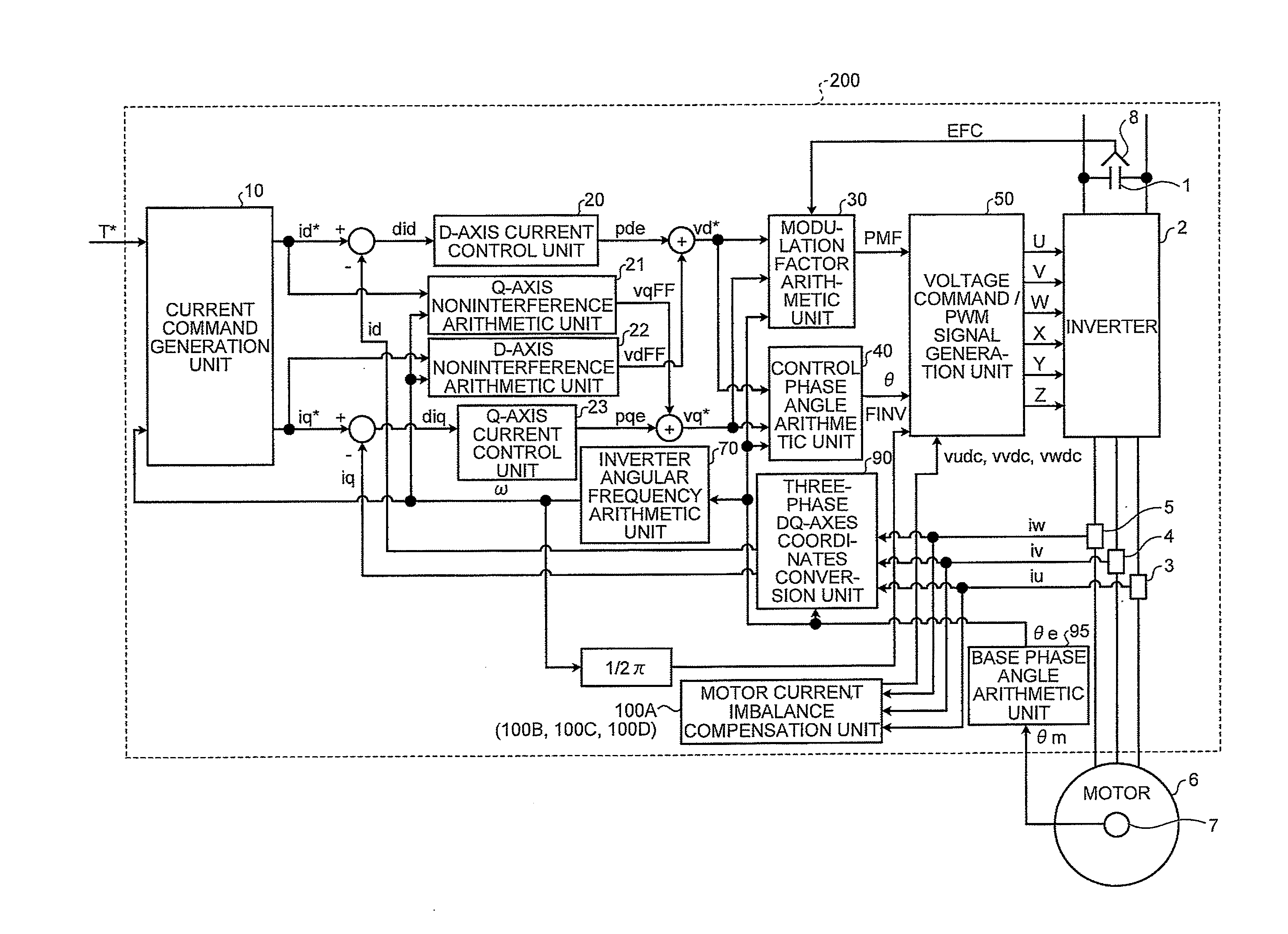
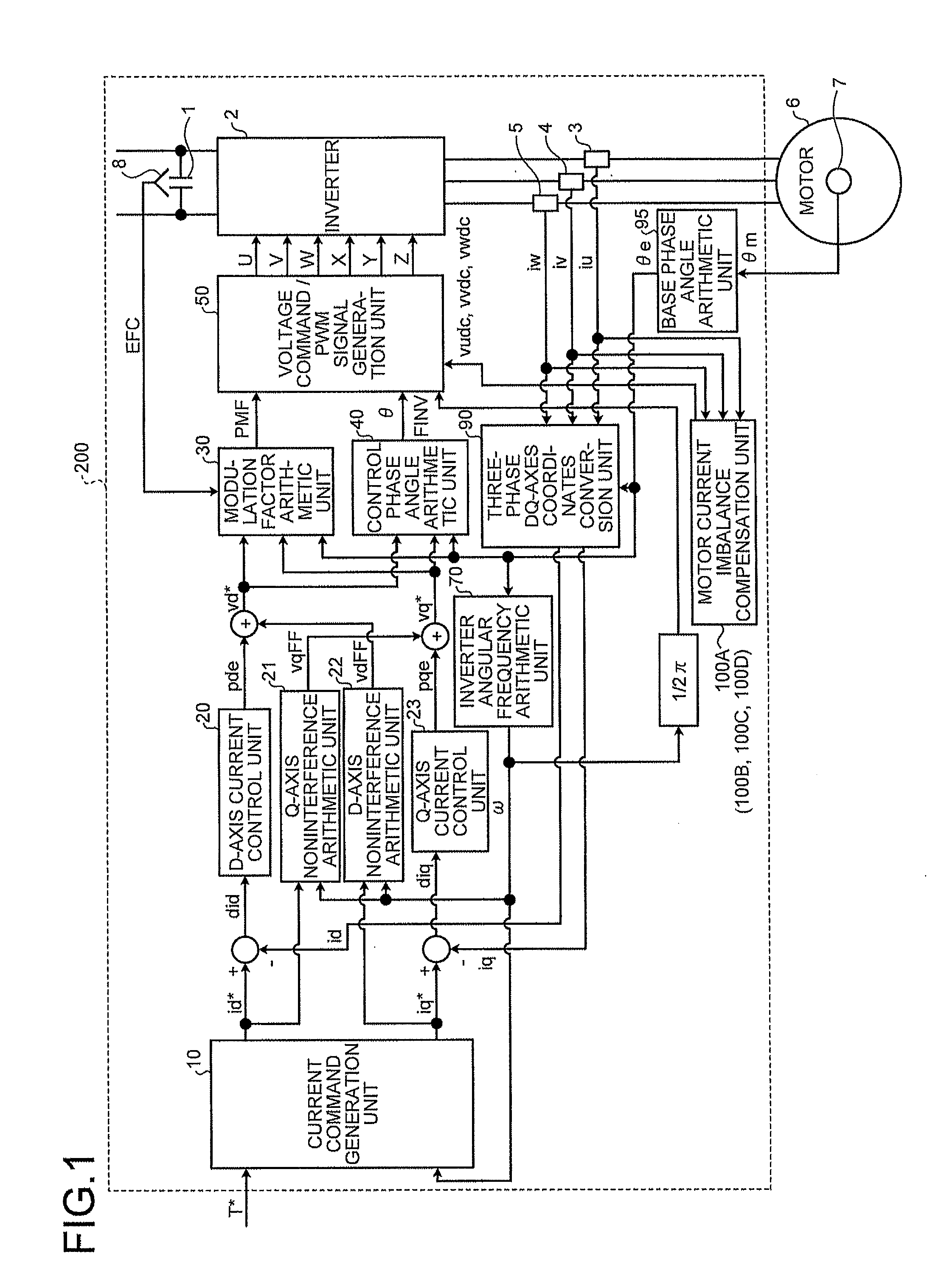
[0065]FIG. 1 is a view illustrating a structural example of a control apparatus of an alternating-current motor according to a first embodiment of the invention. As illustrated in FIG. 1, a main circuit is configured with a capacitor 1 being a direct-current source, an inverter 2 converting direct-current voltage of the capacitor 1 into alternating-current voltage of an arbitrary frequency, and a permanent magnet synchronous motor (hereinafter, simply called a motor) 6. The circuit is provided with a voltage detector 8 to detect voltage of the capacitor 1, and current detectors 3, 4, 5 to respectively detect motor currents iu, iv, iw being output line currents of the inverter 2. The motor 6 is provided with a resolver 7 being a position detector to detect a rotor mechanical angle θm. The detection signals are inputted respectively to units which are described later.
[0066]Here, it is also possible that an encoder is used instead of the resolver 7. Further, it is also possible to adop...
second embodiment
[0093]FIG. 5 is a view illustrating a structural example of the motor current imbalance compensation unit 100B according to the second embodiment of the invention. Since the second embodiment is based on the first embodiment, only the parts different from the configuration of the first embodiment will be described in the following, while description for the parts having the same configuration as the first embodiment will not be repeated. Compared to the first embodiment, as illustrated in FIG. 5, the currents iu, iv of two phases among the three-phase currents iu, iv, iw detected respectively by the current detectors 3, 4, 5 are inputted to the motor current imbalance compensation unit 100B. Then, the unnecessary frequency components are eliminated respectively by the LPFs 101U, 101V. Further, after the polarity is inverted respectively by the gains 102U, 102V, inputting to the proportional integral elements 103U, 103V is performed. The outputs of the proportional integral elements ...
third embodiment
[0096]Next, the configuration of a third embodiment of the invention will be described. Since the third embodiment is based on the first embodiment, only the parts different from the configuration of the first embodiment will be described in the following, while description for the parts having the same configuration as the first embodiment will not be repeated. FIG. 6 is a view illustrating a structural example of the motor current imbalance compensation unit 100C according to the third embodiment of the invention. Compared to the first embodiment, as illustrated in FIG. 6, the currents iu, iv of two phases among the three-phase currents iu, iv, iw detected respectively by the current detectors 3, 4, 5, which are inputted to the motor current imbalance compensation unit 100C. Then, the unnecessary components are eliminated, respectively, by the LPFs 101U, 101V. Further, after the polarity is inverted respectively by the gains 102U, 102V, inputting to the proportional integral eleme...
PUM
 Abstract
Description
Claims
Application Information
 - Generate Ideas
- Intellectual Property
- Life Sciences
- Materials
- Tech Scout
- Unparalleled Data Quality
- Higher Quality Content
- 60% Fewer Hallucinations
Browse by: Latest US Patents, China's latest patents, Technical Efficacy Thesaurus, Application Domain, Technology Topic, Popular Technical Reports.
© 2025 PatSnap. All rights reserved.Legal|Privacy policy|Modern Slavery Act Transparency Statement|Sitemap|About US| Contact US: help@patsnap.com


