Fuel cell system and operating method thereof
a fuel cell and system technology, applied in the direction of fuel cells, solid electrolyte fuel cells, electrical equipment, etc., can solve the problems of cell damage and cell performance decline, and achieve the effect of reducing the performance of the fuel cell, restoring the performance of the polymer electrolyte fuel cell, and minimizing the deterioration of the anod
- Summary
- Abstract
- Description
- Claims
- Application Information
AI Technical Summary
Benefits of technology
Problems solved by technology
Method used
Image
Examples
embodiment 1
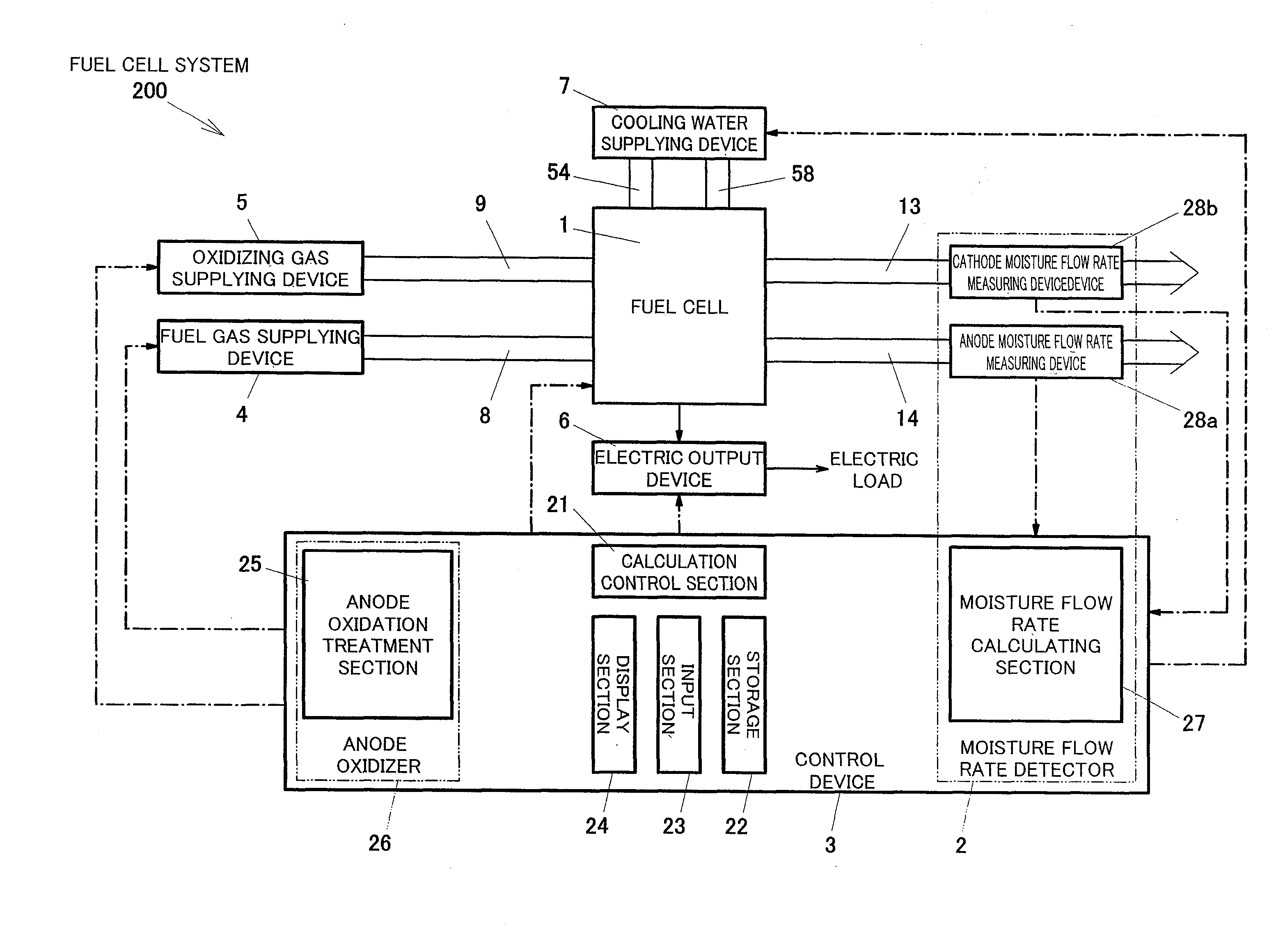
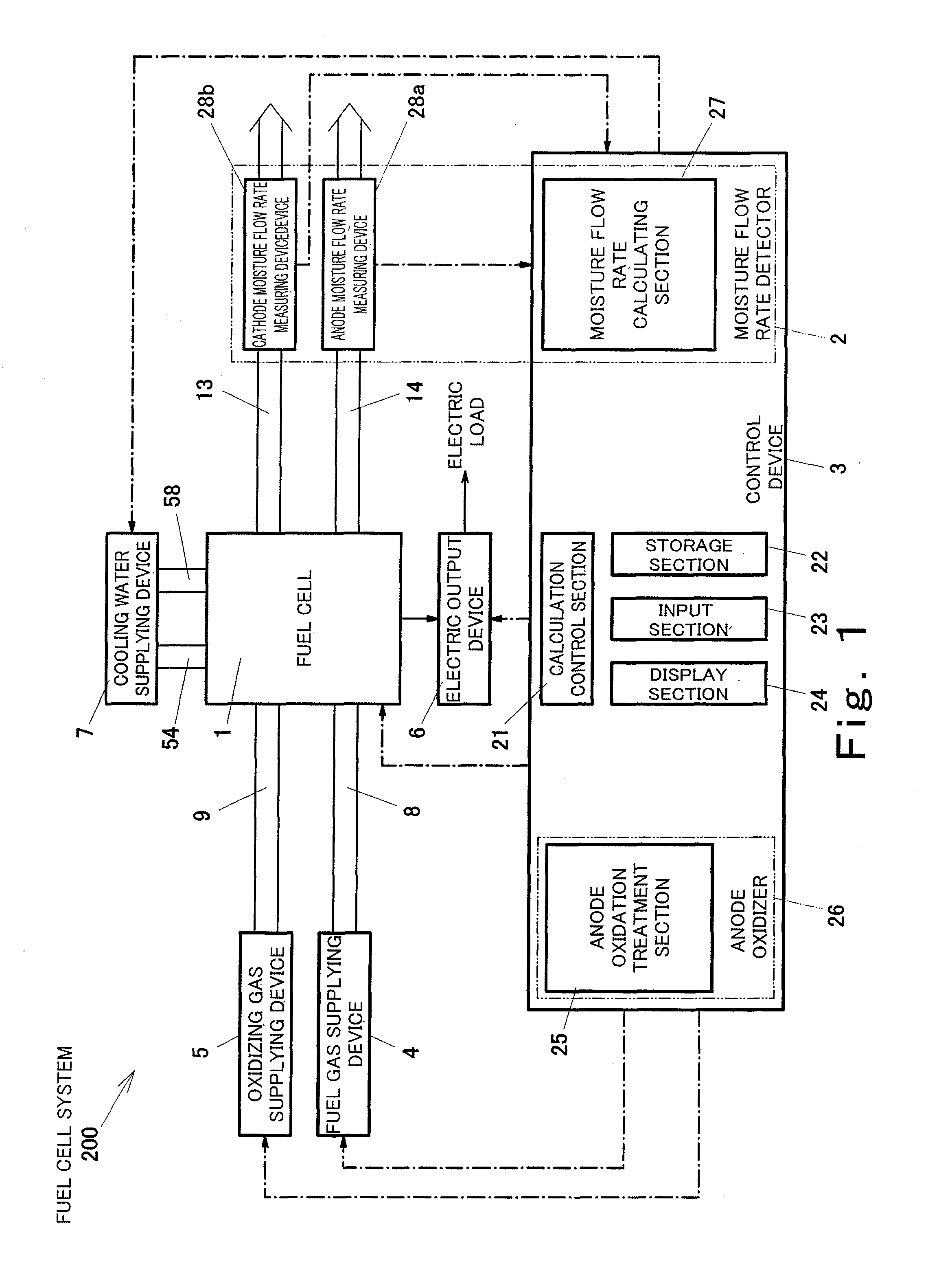
[0154]FIG. 1 is a block diagram schematically showing the configuration of the fuel cell system according to Embodiment 1 of the present invention.
[0155]First, the configuration of the fuel cell system according to Embodiment 1 will be explained.
[0156]As shown in FIG. 1, a fuel cell system 200 according to Embodiment 1 includes a polymer electrolyte fuel cell 1, a moisture flow rate detector 2, a control device 3, a fuel gas supplying device 4, a fuel gas supplying passage 8, an oxidizing gas supplying device 5, an oxidizing gas supplying passage 9, an electric output device 6, and a cooling water supplying device 7.
[0157]The fuel gas supplying passage 8 is connected to the polymer electrolyte fuel cell 1 (hereinafter simply referred to as “fuel cell 1”), and the fuel gas supplying device 4 is connected to the fuel gas supplying passage 8. The fuel gas supplying device 4 supplies a fuel gas to an anode of the fuel cell 1 through the fuel gas supplying passage 8. Herein, the fuel gas...
modification example 1
[0210]FIG. 5 is a schematic diagram showing Modification Example 1 of the moisture flow rate detector 2 in the fuel cell system 200 according to Embodiment 1.
[0211]As shown in FIG. 5, the anode moisture flow rate detector of the moisture flow rate detector 2 in the present modification example is configured to condense the steam, discharged from the anode 16a, into water by bubbling without using the U pipe to detect the flow rate (weight) of moisture per a certain period of time. Specifically, the fuel gas discharging passage 14 includes a measuring container pipe 64. The measuring container pipe 64 is disposed to extend downwardly from the fuel gas discharging manifold (not shown) of the fuel cell 1, penetrate through an upper portion of a measuring container 65, and reach the vicinity of a bottom portion of the measuring container 65. The measuring container 65 stores a predetermined weight of water such that an end portion of the measuring container pipe 64 is immersed in the wa...
modification example 2
[0215]FIG. 6 is a schematic diagram showing Modification Example 2 of the moisture flow rate detector 2 in Embodiment 1.
[0216]As shown in FIG. 6, the moisture flow rate detector 2 (here, the anode moisture flow rate detector) is configured to heat a part of the fuel gas discharging passage 14. Specifically, a heat exchanger 70 is disposed on a portion of the fuel gas discharging passage 14. Then, the unused fuel gas which is discharged from the anode 16a and contains steam and the water flow on one side of the heat exchanger 70, and a combustion gas discharged from the burner of the fuel processor flows on the other side. The heat exchanger 70 carries out heat exchange so as to heat the steam, the unused fuel gas and the water by the combustion gas. A gas flow meter 71 is disposed downstream of the heat exchanger 70. Therefore, all the water discharged from the anode 16a is vaporized, and the flow rate and dew point of the gas containing the generated steam is detected by the gas fl...
PUM
 Abstract
Description
Claims
Application Information
 - R&D
- Intellectual Property
- Life Sciences
- Materials
- Tech Scout
- Unparalleled Data Quality
- Higher Quality Content
- 60% Fewer Hallucinations
Browse by: Latest US Patents, China's latest patents, Technical Efficacy Thesaurus, Application Domain, Technology Topic, Popular Technical Reports.
© 2025 PatSnap. All rights reserved.Legal|Privacy policy|Modern Slavery Act Transparency Statement|Sitemap|About US| Contact US: help@patsnap.com


