Flexible extendable stent and methods of surface modification therefor

a flexible, stent technology, applied in the field of medical stents, can solve the problems of many commercially available coated stents suffering from problems, stents can potentially impede the flow of blood, and many commercially available stents suffer from complications, etc., to achieve excellent biomechanical properties and optimal surfaces

Inactive Publication Date: 2010-08-12
CORNOVA
View PDF5 Cites 6 Cited by
  • Summary
  • Abstract
  • Description
  • Claims
  • Application Information

AI Technical Summary

Benefits of technology

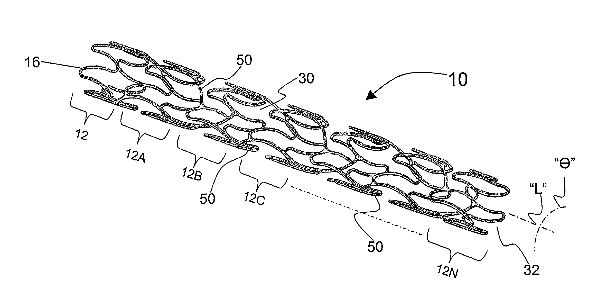
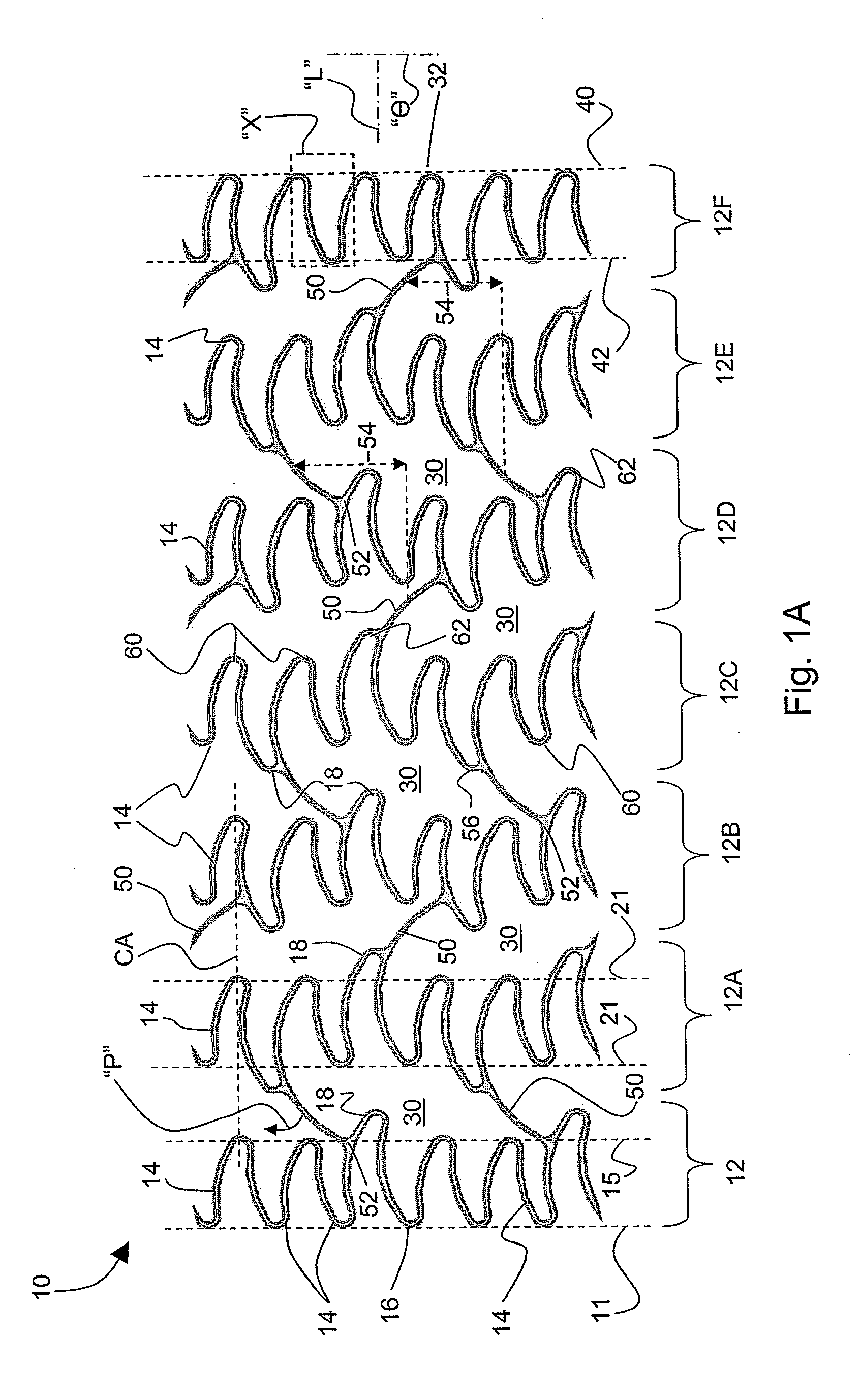
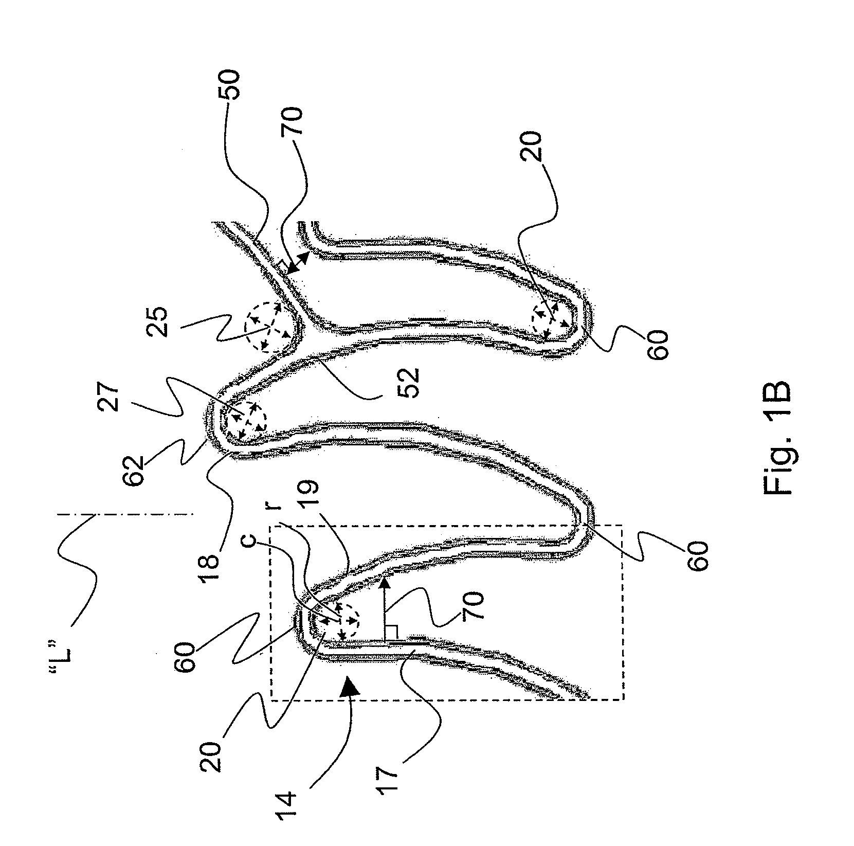
[0013]Embodiments of the present invention relate to medical stent assemblies comprised of elongated tubular patterns of metal capable of expanding and propping open a vessel or duct within a living, human being. It is one object of the present invention to provide a substrate structure with curvilinear features optimized for providing excellent bio-mechanical properties (e.g. even expansion, retention force, flexibility, strength, avoidance of foreshortening) in acting as a vessel prosthesis while permitting the application of relatively thin, smooth, and / or even surface-enhancing coatings. Embodiments of the invention can provide particularly optimal surfaces for coating applications involving the use of spraying or bombarding particles about the substrate structure such as with, for example, ion-assisted deposition.

Problems solved by technology

As a foreign object inserted into a vessel, a stent can potentially impede the flow of blood.
This effect can also be exacerbated by the undesired growth of tissue and on and around the stent, potentially leading to complications including thrombosis and restenosis.
However, many commercially available coated stents suffer from problems including corrosion, flaking, cracking, and other strut and surface imperfections.
The effects of flaking or cracking of surface materials, which create a less smooth surface and can also substantially negate anti-growth properties, may even cause a serious blockage resulting in death.
Many of these problems arise because of the difficulty in effectively coating the thin, angular struts of a typical stent which must undergo flexing and deformation during deployment.
The resulting complex patterns that embody many stents thus often require complex, expensive coating and / or other surface modification mechanisms.
For example, an area of a stent strut pattern with sharply angular features may inordinately block some of a surface modification process, including a cleaning process, and further block a coating material from evenly collecting and adhering along these features.
When a spraying or bombardment type of process is employed, the heavy angularity and irregularity of the surface makes uniformly targeting the irregularly featured and / or curved surfaces highly challenging.
The increased thickness of a coating can reduce the flexibility of the stent and / or increase the likelihood of cracking.
Another complication that can occur in areas of sharp angularity is “webbing,” where areas between closely spaced surfaces can essentially be filled in with material, causing the coating to split and / or flake when the area opens during expansion of the stent.
Furthermore, these areas of highly angular and / or irregular shapes can be inherently more susceptible to cracking with or without coatings due to the stresses they undergo when flexing occurs during expansion.

Method used


Image

  • Flexible extendable stent and methods of surface modification therefor
  • Flexible extendable stent and methods of surface modification therefor
  • Flexible extendable stent and methods of surface modification therefor

Examples


Embodiment Construction

[0076]The accompanying drawings are described below, in which example embodiments in accordance with the present invention are shown. Specific structural and functional details disclosed herein are merely representative. This invention may be embodied in many alternate forms and should not be construed as limited to example embodiments set forth herein.

[0077]Accordingly, specific embodiments are shown by way of example in the drawings. It should be understood, however, that there is no intent to limit the invention to the particular forms disclosed, but on the contrary, the invention is to cover all modifications, equivalents, and alternatives falling within the spirit and scope of the claims. Like numbers refer to like elements throughout the description of the figures.

[0078]It will be understood that, although the terms first, second, etc. may be used herein to describe various elements, these elements should not be limited by these terms. These terms are used to distinguish one e...


PUM


Abstract

Stent strut and surface geometries are provided for enhancing surface coating applications while providing highly beneficial biomechanical properties. A low-profile, flexible, expandable, elongated, stent assembly is provided and defined by a structure of connected circumferential arrays of webs or bends, the webs or bends and their connections having limited degrees of curvature that help avoid interference during various surface-modifying and surface-enhancing processes.

Description

RELATED APPLICATIONS[0001]This application is a continuation-in-part of U.S. patent application Ser. No. 11 / 613,443 filed on Dec. 20, 2006, which is a continuation-in-part of U.S. patent application Ser. No. 29 / 252,668 filed Jan. 25, 2006, issued as U.S. Patent No. D553,746 and U.S. application Ser. No. 29 / 252,669 filed Jan. 25, 2006, issued as U.S. Pat. No. D553,747, the contents of each of which are herein incorporated by reference in their entirety. This application is also a continuation-in-part of U.S. patent application Ser. No. 11 / 843,376 filed on Aug. 22, 2007, published on Jul. 24, 2008 as U.S. Patent Application Publication No. 2008-0177371-A1 and U.S. patent application Ser. No. 11 / 843,402 filed on Aug. 22, 2007, published on Sep. 4, 2008 as U.S. Patent Application Publication No. 2008-0215132-A1, the contents of each of which are herein incorporated by reference in their entirety. This application claims the benefit of U.S. Patent Application No. 61 / 013,246 filed on Dec....

Claims


Application Information

Patent Timeline
Patent Type & Authority Applications(United States)
IPC IPC(8): A61F2/06B05D1/12
CPCA61F2/91A61F2/915A61F2002/91508A61F2002/91516A61F2002/91525A61F2002/9155A61F2002/91583A61F2230/0054
Inventor FLIEDNER, THILO U.RYAN, ERIC S.
Owner CORNOVA
Why Eureka
Try Eureka