
Electrolyzed water manufacturing device, electrolyzed water manufacturing method, and electrolyzed water

a technology of electrolyzed water and manufacturing device, which is applied in the direction of electrolysis, electrolysis components, electrodialysis, etc., can solve the problems of inability to maintain the antimicrobial strength required, inability to apply, and inability to work well, so as to achieve the effect of suppressing secondary electrolysis

Inactive Publication Date: 2010-08-12
ARAI YUSHO
View PDF9 Cites 19 Cited by
  • Summary
  • Abstract
  • Description
  • Claims
  • Application Information

AI Technical Summary

Benefits of technology

[0008]Furthermore, in the electrolyzed water producing method disclosed in Reference 2, a three-tank method is used for the electrolysis chambers, where an aqueous electrolytic solution, such as saline solution, is stored in the electrolytic chamber in the middle, and tap water or water filtered through a water filter, is contained in the anode and cathode electrolysis chambers on both sides, and is electrolyzed. In the electrolysis process wherein the aqueous electrolytic solution is stored in the middle electrolysis chamber, there is the benefit of being able to produce efficiently, with a low voltage, low current, and a short time, acidic electrolyzed water and alkaline electrolyzed water that do not include sodium chloride. However, because all three of the electrolysis chambers function in a batch-wise process, not only does this approach not work well with mass production, but also there is no concept whatsoever of producing electrolyzed water that contains hypochlorous acid that is adjusted so as to be weakly acidic, neutral, or weakly alkaline through mixing or blending the acidic electrolyzed water and the alkaline electrolyzed water.
[0047]In the present invention, the plurality of compartments in the middle chamber may be partitioned by respective dividing portions. The water that is electrolyzed is retained by partitioning by the dividing portions, enabling the achievement of more efficient electrolysis.

Problems solved by technology

As a result, it is difficult to maintain the antimicrobial strength required in the acidic electrolyzed water over an extended period of time due to the gasification that occurs to the hypochlorous acid over a short period of time, and thus there is a problem in that there is a limitation to the application thereof.
However, because all three of the electrolysis chambers function in a batch-wise process, not only does this approach not work well with mass production, but also there is no concept whatsoever of producing electrolyzed water that contains hypochlorous acid that is adjusted so as to be weakly acidic, neutral, or weakly alkaline through mixing or blending the acidic electrolyzed water and the alkaline electrolyzed water.
Note that while acidic or alkaline electrolyzed water is being produced through the electrolysis methods that use either the two-chamber or the three-chamber electrolysis tanks as set forth in the prior art, it is difficult to cause the effective chlorine concentration of the electrolyzed water that is produced to be within a specific range, and difficult to adjust the pH value between being weakly acidic and weakly alkaline.
Furthermore, in the method of electrolysis using the two-chamber or the three-chamber electrolysis tanks, there is essentially no manufacturing of sodium hypochlorite.

Method used


Image

  • Electrolyzed water manufacturing device, electrolyzed water manufacturing method, and electrolyzed water
  • Electrolyzed water manufacturing device, electrolyzed water manufacturing method, and electrolyzed water
  • Electrolyzed water manufacturing device, electrolyzed water manufacturing method, and electrolyzed water

Examples


first modified example

(1) First Modified Example

[0145]Pores may be provided in the first partitioning membrane 24 that is made out of a cation exchange membrane. The diameters of the pores may be, for example, between 30 and 80 μm. In this case, the first partitioning membrane 24 may be structured from a non-woven fabric.

[0146]Doing so facilitates the movement of the sodium ions, and the like, in the aqueous electrolytic solution moving into the anode chamber 20, making it easier to produce a mixed water of sodium hypochlorite and hypochlorous acid.

second modified example

(2) Second Modified Example

[0147]As illustrated in FIG. 5 through FIG. 9, the cathode 32 may be covered with a sheet member that is permeable to water. As the sheet member 90, a non-woven fabric or a multilayer mesh sheet, for example, may be used. The following benefits are achieved by covering the cathode 32 with a sheet member in this way.

[0148]Covering the cathode 32 with the sheet member 90 causes the electrolyzed water to be retained near the cathode 32. Because of this, the amount of charge is increased relative to the water that is retained near the cathode 32. The amount of increase in the charge relative to the water further reduces the scaling that adheres, based on the anions. The result not only facilitates continuous operation, but is able to eliminate or reduce the frequency of reverse cleaning of the cathode 32, enabling the achievement of an electrolysis device that is more useful in an industrial application. At the same time, this is able to prevent the ion exchan...

third modified example

(3) Third Modified Example

[0150]While in the form of embodiment set forth above, the anode chamber 20 and the cathode chamber 30 were connected by a connecting hole 52 in the partitioning wall 50, instead they may be connected by a connecting passage 54 provided separately, as illustrated in FIG. 11. The connecting passage 54 has the benefit of making it easier to understand the amount of water that moves between the anode chamber 20 and the cathode chamber 30. An adjustable valve 56 may be provided in the connecting passage 54. The amount of water moving between the anode chamber 20 and the cathode chamber 30 can be adjusted using the adjustable valve 56.

(4) Forth Modified Example

[0151]As illustrated in FIG. 12, a first gas removing opening 28c may be provided for removing the gas that is produced in the anode chamber 20. Doing so makes it possible to exhaust the gas that is produced in the anode chamber 20, making it possible to prevent instability in flow due to the gas. Addition...


PUM

PropertyMeasurementUnit
Timeaaaaaaaaaa
Ratioaaaaaaaaaa
Heightaaaaaaaaaa

Abstract

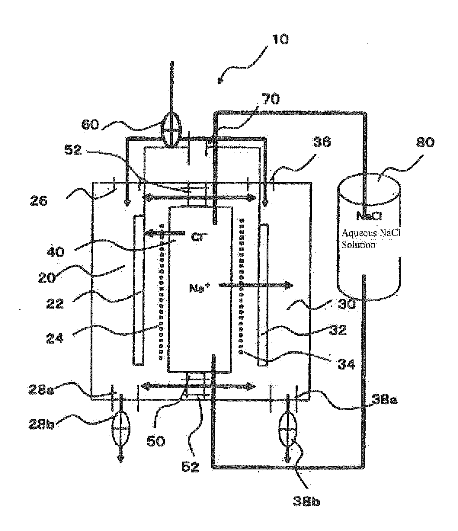
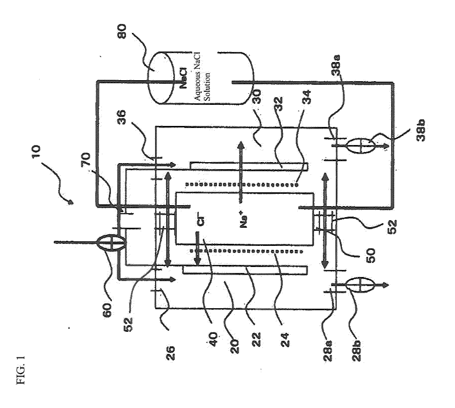
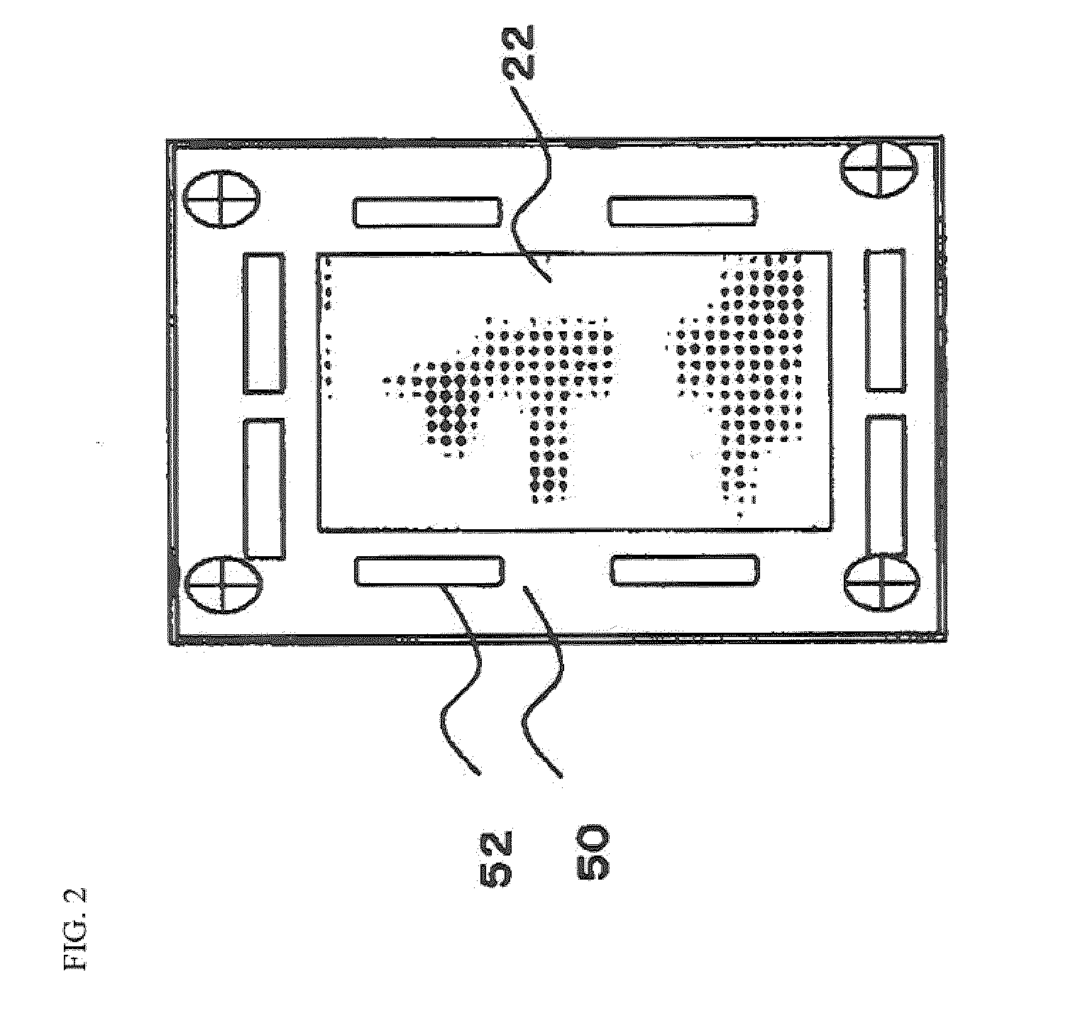
Disclosed is an electrolyzed water manufacturing method and electrolyzed water manufacturing device capable of producing efficiently weakly acidic through weakly alkaline electrolyzed water, and capable of producing said electrolyzed water on a large scale. The electrolyzed water manufacturing device 10 comprises: an anode chamber 20 that is provided with an anode electrode 22; a cathode chamber 30 that is provided with a cathode electrode 32; a middle chamber 40 for containing an aqueous electrolytic solution, disposed between the anode chamber 20 and the cathode chamber 30; an anion exchange membrane 24 for partitioning between the anode chamber 20 and the middle chamber 40; and a cation exchange membrane 34 for partitioning between the cathode chamber 30 and the middle chamber 40. The anode chamber 20 and the cathode chamber 30 are connected by a connecting hole 52 provided in a partitioning wall 50.

Description

FIELD OF THE INVENTION[0001]The present invention relates to an electrolyzed water manufacturing device having a middle chamber for containing an aqueous electrolytic solution, to an electrolyzed water manufacturing method that uses the electrolyzed water manufacturing device, and to electrolyzed water obtained using the electrolyzed water manufacturing method.PRIOR ART[0002]As a typical electrolyzed water producing device there is the producing device of a type with one tank or of a type with two tanks (chambers). For example, an aqueous electrolytic solution, such as a saline solution, and an anode plate and a cathode plate are provided, and an electrolyzed water that contains sodium chloride is produced through an electrolysis process wherein an electric current is caused to flow through the anode plate and the cathode plate. Note that not only is toxic trihalomethane produced in this electrolysis process, but the sodium chloride remains as-is.[0003]Additionally, structure disclo...

Claims


Application Information

Patent Timeline
IPC IPC(8): C02F1/461C25B9/08C25B15/08C25B9/19
CPCB01D61/46B01D2313/083B01D2313/18C02F1/46109C02F2201/46185C02F2001/46119C02F2001/46157C02F2201/46115C02F2201/46145C02F1/4618B01D61/44B01D2313/345C02F1/4674B01D61/463
Inventor ARAI, YUSHO
Owner ARAI YUSHO
Learn More