Coating method and apparatus, a permanent magnet, and manufacturing method thereof

a technology of permanent magnets and coating methods, applied in the direction of magnetic materials, evaporation applications, magnetic bodies, etc., can solve the problems of greatly reduced maximum energy products exhibiting magnetic properties, heat deformation, and reduced magnetic field strength, so as to achieve high efficiency, low cost, and high speed

Active Publication Date: 2010-06-24
ULVAC INC
View PDF3 Cites 6 Cited by
  • Summary
  • Abstract
  • Description
  • Claims
  • Application Information

AI Technical Summary

Benefits of technology

[0038]The permanent magnet and its manufacturing method of the present invention have effects that the magnet can be manufactured at a high productivity and a low cost with effectively using Dy and Tb of coating materials and coating them at a high speed on the surface of magnet of Fe—B-rare earth elements having a predetermined configuration and that the magnet has excellent corrosion resistance and weather resistance without any additional protective film.
[0039]In addition, the coating method and apparatus of the present invention have effects that they can carry out coating of vaporizable metallic material at high yield and speed and substantially uniformly on a whole surface of the magnet having a predetermined configuration and are especially suitable for coating of vaporizable metallic material including Dy and Tb on a surface of magnet of Fe—B-rare earth elements having a predetermined configuration.

Problems solved by technology

On the other hand the sintered magnet of Nd—Fe—B has a problem that it is demagnetized by heat when it is heated beyond its predetermined temperature since its Curie temperature is low such as 300° C.
However, since Dy and Tb take the ferrimagnetism structure in which Dy and Tb take a spin orientation opposite to that of Nd in the principal phase crystal lattice, it is caused a problem that the magnetic field strength, therefore the maximum energy product exhibiting the magnetic properties is greatly reduced.

Method used


Image

  • Coating method and apparatus, a permanent magnet, and manufacturing method thereof
  • Coating method and apparatus, a permanent magnet, and manufacturing method thereof
  • Coating method and apparatus, a permanent magnet, and manufacturing method thereof

Examples


embodiment 1

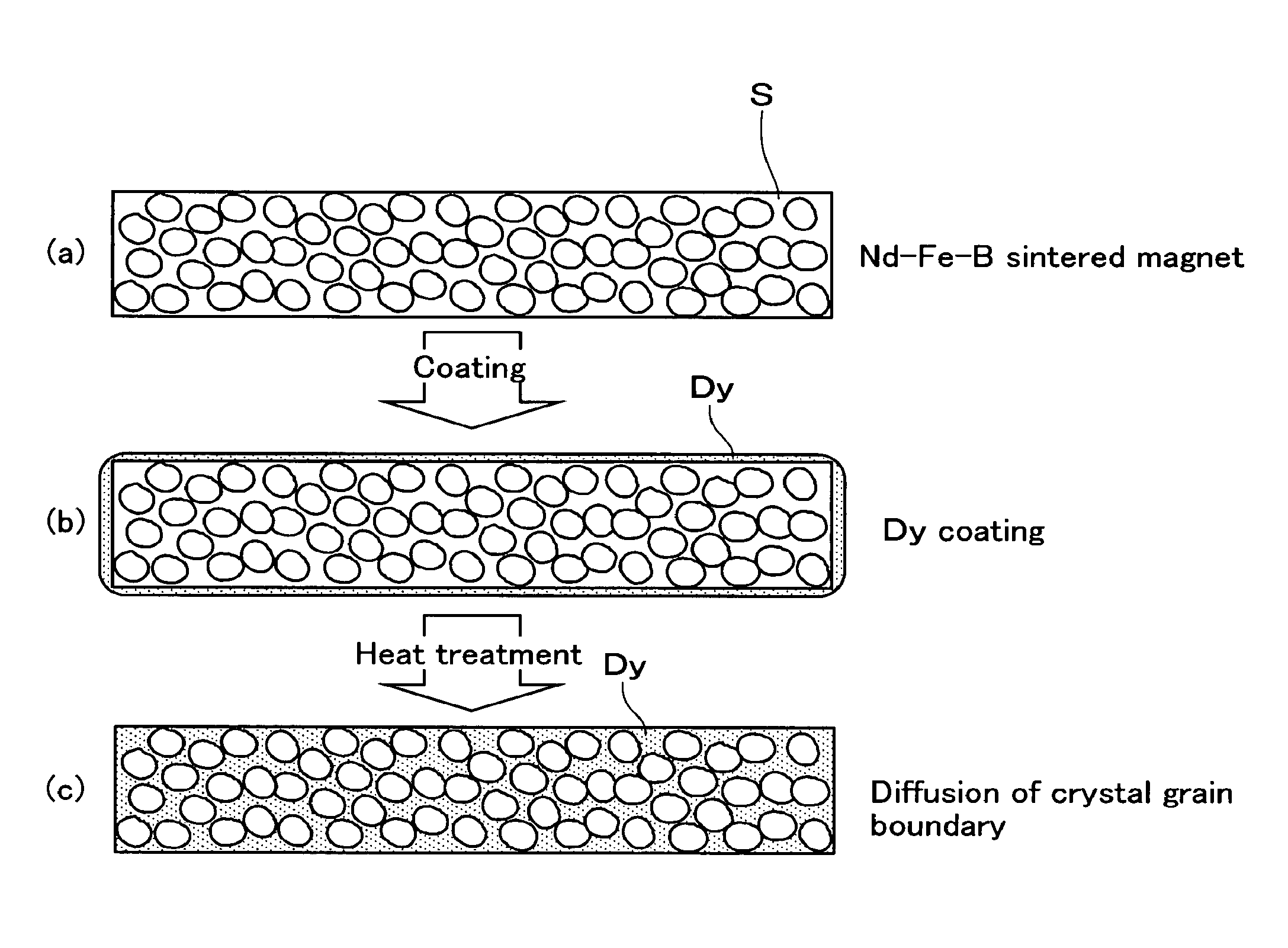
[0083]Each sintered magnet of Fe—B-rare earth elements was made as a rectangular parallelopiped of 50×50×8 mm using a raw material having a composition of 31Nd-1Co-1B-0.1Cu-bal.Fe (“NEOMAX-50 manufactured by NEOMAX Co.). The surface of sintered magnet S was cleaned using acetone after having finished it as having a surface roughness of less than 20 μm.

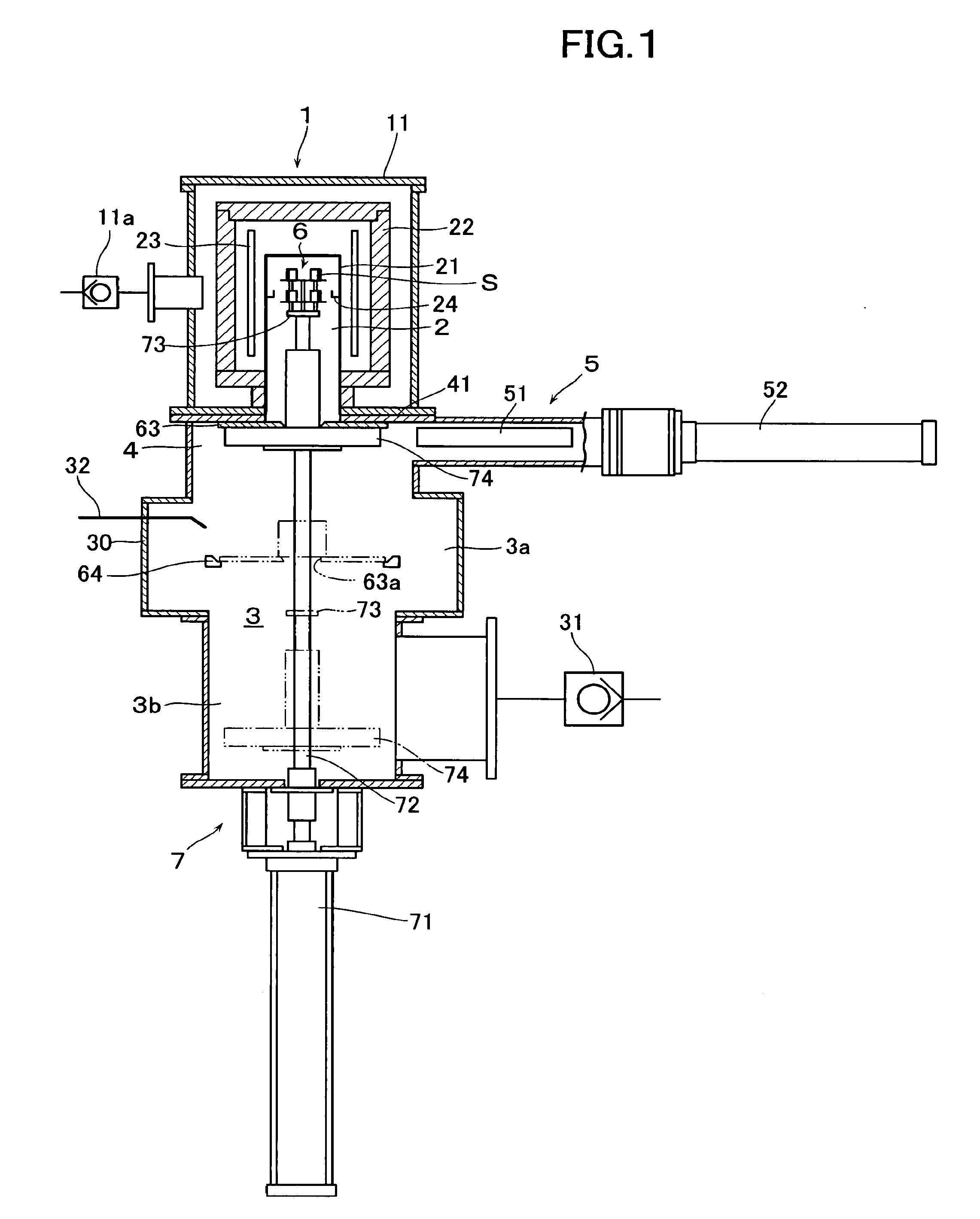
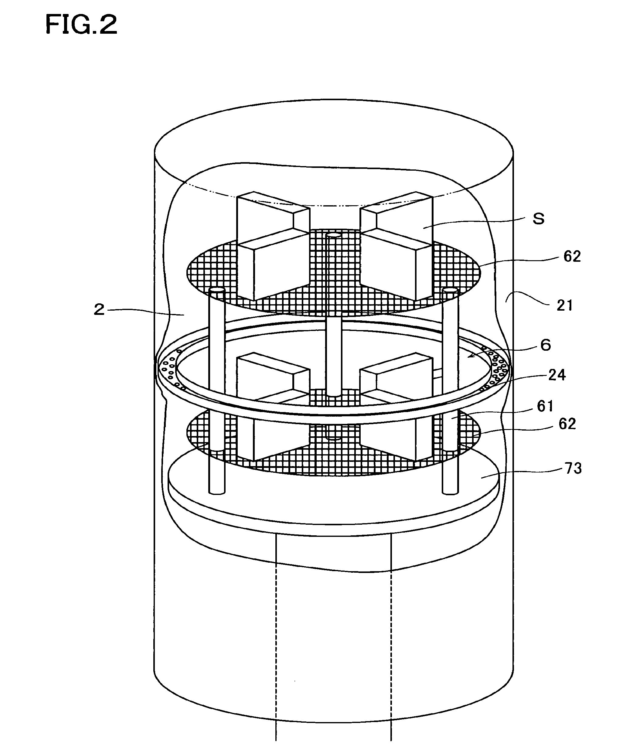
[0084]Dy was coated on the surface of sintered magnet S using the coating apparatus 1 and method of the present invention. Dy of 99.9% degree of purity was used as the coating material and Dy of gross 500 g was laid on the receptor 24. A wire forming the mesh type supporting member 62 of the supporting means 6 is made of Mo and has a diameter of 1 mm. Then four (4) cleaned sintered magnets S were laid on each supporting members 62 on a circle of a diameter (80 mm) oppositely in a diametrical direction each other (totally eight (8) sintered magnets S were placed on two supporting members 62 of upper and lower stages. A space between the...

embodiment 2

[0088]In this embodiment 2, permanent magnets were manufactured at same conditions as those in the embodiment 1 except for that heat treatment was not carried out. However, the holding time duration of the permanent magnets within the Dy vapor atmosphere was set at one (1) minute and the temperature within the process chamber was varied. FIG. 6 is a table showing average values of a coating thickness of Dy when the coating was carried out under these conditions, and the magnetic properties of permanent magnets manufactured in this embodiment. According to this embodiment 2, it can be found that little coating is formed at a temperature lower than 1,000° C., but coating can be formed at a high speed more than 20 μm / sec at a temperature higher than 1,200° C. In this case, it is found that it is possible to obtain a permanent magnet having a maximum energy product of about 50 MG0e of little loss and a high coercive force of 17 K0e or more in a range of 1,100˜1,700° C.

embodiment 3

[0089]In this embodiment 3, permanent magnets were manufactured at same conditions as those in the embodiment 1 except for that pretreatment (cleaning treatment) was not carried out. However, the holding time duration of the permanent magnets within the Dy vapor atmosphere was varied. FIG. 7 is a table showing average values of the coating thickness of Dy coated with the holding time duration being varied, the maximum and the magnetic properties of permanent magnets manufactured in this embodiment. According to this embodiment 3, it can be found that a vapor depositing velocity exceeding 17 μm can be obtained and the temperature rise of sintered magnet itself is at most 743° C. although it is held for 60 seconds. In this case, it is found that it is possible to obtain a permanent magnet of high coercive force having a maximum energy product of about 50 MG0e, a remanent magnetic flux density of 14.5 kG and a coercive force of 15.4˜21.3 K0e.


PUM

PropertyMeasurementUnit
temperatureaaaaaaaaaa

Abstract

The object of the present invention is to improve the productivity of a permanent magnet and to manufacture it at a low cost by effectively coating Dy and Tb on a surface of the magnet of Fe—B-rare earth elements having a predetermined configuration. The permanent magnet of the present invention is manufactured by a coating step for coating Dy on the surface of the magnet of Fe—B-rare earth elements having a predetermined configuration and a diffusing step for diffusing Dy coated on the surface of the magnet into crystal grain boundary phases of the magnet with being heat treated at a predetermined temperature. In this case, the coating step comprises a first step for heating a process chamber used for carrying out the coating step and generating metallic vapor atmosphere within the process chamber by vaporizing vaporizable metallic material previously arranged within the process chamber, and a second step for introducing into the process chamber the magnet held at a temperature lower than that within the process chamber and then selectively depositing the vaporizable metallic material on a surface of the magnet by an effect of temperature difference between the temperature within the process chamber and that of the magnet by the magnet reaches a predetermined temperature.

Description

[0001]This application is a divisional under 35 U.S.C. §120 of U.S. patent application Ser. No. 11 / 886,629, filed on Sep. 18, 2007, which was a U.S. national phase patent application under 35 U.S.C. §371 of PCT Patent Application No. PCT / JP2006 / 305034, filed on Mar. 14, 2006, which claims priority under 35 U.S.C. §119 to Japanese Patent Application No. 2005-080021, filed on Mar. 18, 2005, all of which are incorporated in their entireties by reference.BACKGROUND OF THE INVENTION[0002]1. Field of the Invention[0003]The present invention relates to coating method and apparatus, a permanent magnet, and a manufacturing method thereof, and more particularly to a permanent magnet and a manufacturing method thereof in which the permanent magnet is manufactured by coating vaporizable metallic material including at least one of Dy and Tb on a surface of a magnet of Fe—B-rare earth elements, and then diffusing at least one of Dy and Tb into crystal grain boundary phases of a sintered magnet by...

Claims


Application Information

Patent Timeline
Patent Type & Authority Applications(United States)
IPC IPC(8): B05D3/02B05D5/00B05D7/14
CPCC23C14/16C23C14/243C23C14/541H01F41/0293H01F10/126H01F41/20H01F1/0571C23C14/54C23C14/22H01F10/12
Inventor NAGATA, HIROSHISHINGAKI, YOSHINORI
Owner ULVAC INC
Why Eureka
Try Eureka