
Methods For Forming Activated Carbon Material For High Energy Density Ultracapacitors

a technology of activated carbon and ultracapacitors, which is applied in the field of carbon-based electrodes, can solve the problems of high cost of such carbon-based electrodes, and achieve the effects of high cost of synthetic resins, high cost of such carbon-based electrodes, and high energy density devices

Active Publication Date: 2010-06-17
CORNING INC
View PDF29 Cites 42 Cited by
  • Summary
  • Abstract
  • Description
  • Claims
  • Application Information

AI Technical Summary

Benefits of technology

[0003]Carbon-based electrodes suitable for incorporation into high energy density devices are known. For example, high performance carbon materials, which form the basis of such electrodes, can be made from synthetic phenolic resin precursors. However, due to the high cost of the synthetic resins, the cost of such carbon-based electrodes can be high. Accordingly, it would be an advantage to provide a more economical carbon material that can be used to form carbon-based electrodes that enable higher energy density devices.

Problems solved by technology

However, due to the high cost of the synthetic resins, the cost of such carbon-based electrodes can be high.

Method used


Image

  • Methods For Forming Activated Carbon Material For High Energy Density Ultracapacitors
  • Methods For Forming Activated Carbon Material For High Energy Density Ultracapacitors
  • Methods For Forming Activated Carbon Material For High Energy Density Ultracapacitors

Examples


example 1

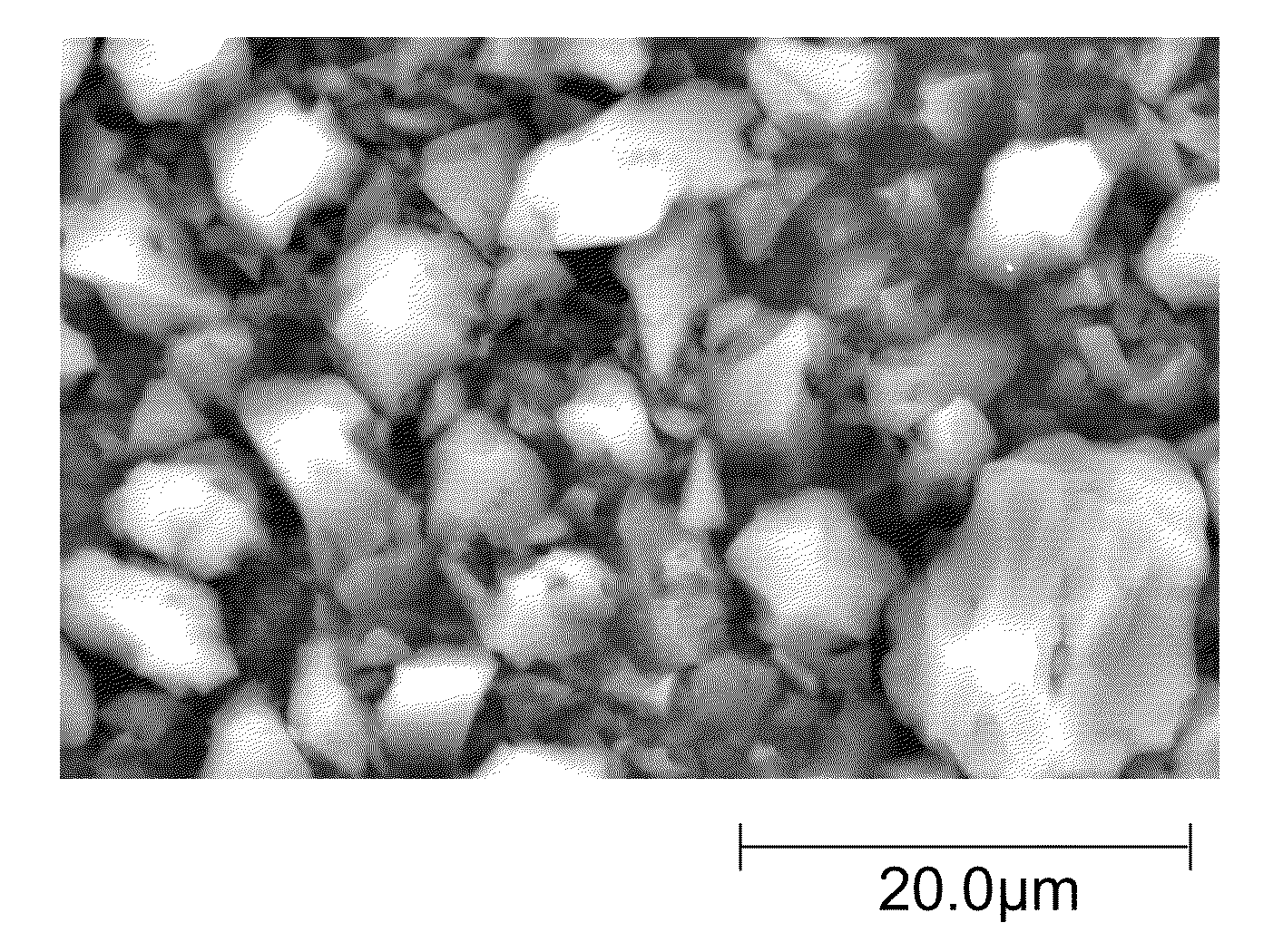
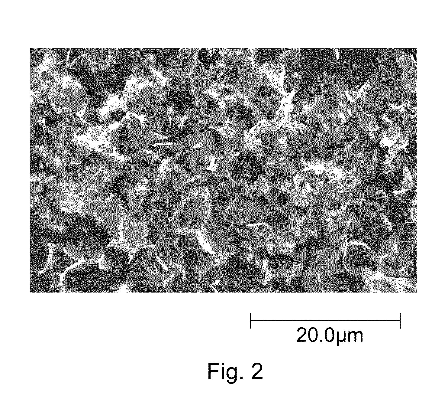
[0039]Wheat flour was first carbonized in flowing nitrogen at 800° C. for 2 hours. The resulting carbonized precursor was then mixed with a KOH solution (46 wt. % in water) in 1:5 (wt. / wt.) ratio of carbon:KOH. The mixture was heated in nitrogen to 800° C. for 2 hours and cooled to room temperature. The cooled mixture was washed with water and then with dilute HCl to remove potassium. Complete elimination of potassium was confirmed by monitoring the pH of the effluent. The carbon powder product was dried and ground to a fine powder (˜10 micrometers).

[0040]Eighty grams of the carbon powder was mixed with 10 grams of carbon black and 10 grams of PTFE to obtain a well-mixed mass. This mixture was then rolled on a roll mill to obtain a well-knit film having a thickness of about 100 micrometers. Carbon-based electrodes were produced by stamping the thin film.

[0041]The carbon-based electrodes were soaked in 1.5 M tetraethylammonium-tetrafluoroborate (TEA-TFB) in acetonitrile. A porous sep...

example 2

[0042]The experiment of Example 1 was repeated, except corn flour was substituted for wheat flour. The volumetric capacitance of the activated carbon electrode was 97 F / cm3.

example 3

Comparative

[0043]A comparative, resin-based carbon material was prepared by combining an aqueous solution of KOH (45 wt. %) with an aqueous phenolic resin (Georgia Pacific GP® 510D34) in a ratio of 3:1 by weight. The mixture was cured by heating in an oven at 125° C. for 24 hours and then at 175° C. for 24 hours to obtain a foam-like solid with a brown-yellow color. The cured mixture was broken into small pieces by mechanical force, placed in a graphite crucible and loaded in a retort furnace (CM Furnaces, Model 1216FL) for carbonization / activation.

[0044]The furnace temperature was ramped up at a rate of 200° C. / hr to 800° C., held at 800° C. for 2 hours, and then cooled down naturally. Throughout the heating cycle, the furnace was purged with nitrogen gas.

[0045]After cooling to ambient temperature, the carbon material was soaked in DI water for a few minutes, filtered, soaked in a known amount of 37% HCl solution (2 mL for every 1 g of carbon) for an hour, filtered, and then washed...


PUM


Abstract

A method for producing an activated carbon material includes forming an aqueous mixture of a natural, non-lignocellulosic carbon precursor and an inorganic compound, heating the mixture in an inert or reducing atmosphere, cooling the heated mixture to form a first carbon material, and removing the inorganic compound to produce an activated carbon material. The activated carbon material is suitable to form improved carbon-based electrodes for use in high energy density devices.

Description

BACKGROUND AND SUMMARY[0001]The present invention relates to carbon-based electrodes and, more specifically, to porous activated carbon material and methods for preparing an activated carbon material for use in making such electrodes. The invention also relates to high power density energy storage devices comprising carbon-based electrodes.[0002]Energy storage devices such as ultracapacitors may be used in many applications where a discrete power pulse is required. Such applications range from cell phones to hybrid vehicles. An important characteristic of an ultracapacitor is the energy density that it can provide. The energy density of the device, which can comprise two or more carbon-based electrodes separated by a porous separator and / or an organic electrolyte, is largely determined by the properties of the carbon-based electrodes.[0003]Carbon-based electrodes suitable for incorporation into high energy density devices are known. For example, high performance carbon materials, wh...

Claims


Application Information

Patent Timeline
IPC IPC(8): C01B31/02H01M4/88C01B32/336
CPCC01B31/125H01M4/133H01M4/583Y02E60/122H01M4/00H01G11/44H01M4/86H01M4/02C01B31/08H01G11/34H01M4/88C01P2004/61C01P2006/12C01P2006/40C01P2004/03Y02E60/13C01B32/30C01B32/348C01B32/318Y02E60/50Y02E60/10H01G11/86
Inventor GADKAREE, KISHOR PURUSHOTTAMMACH, JOSEPH FRANK
Owner CORNING INC
Learn More