
Phthalamide-lanthanide complexes for use as luminescent markers

a technology of phthalamidelanthanide and complexes, which is applied in the field of phthalamidelanthanide complexes for luminescent markers, can solve the problems of labeling, high cost, hazardous use, and labeling must be washed from the probe and its fluorescence developed, and achieves high quantum yield, high stability and solubility of these complexes. , the effect of extreme luminescen

Inactive Publication Date: 2005-03-08
RGT UNIV OF CALIFORNIA
View PDF5 Cites 49 Cited by
  • Summary
  • Abstract
  • Description
  • Claims
  • Application Information

AI Technical Summary

Benefits of technology

The present invention provides a new class of lanthanide-complexing ligands that incorporate hydroxyisophthamidylic acid moieties within their structures and luminescent metal complexes of these ligands. These compounds have many features desired for fluorescent markers and probes of use in fluorescent assay systems, such as high quantum yields of lanthanide ion fluorescence, high stability and solubility in water, easy synthesis with inexpensive starting materials, and facile access to many derivatives for linking these probes to other molecules. The invention also provides methods for detecting small molecular bioactive materials and biomolecules at trace concentrations without using radioactive species.

Problems solved by technology

For example, radioactive labels are quite versatile, and can be detected at very low concentrations, such labels are, however, expensive, hazardous, and their use requires sophisticated equipment and trained personnel.
A disadvantage, however, of these types of assays is that the label must be washed from the probe and its fluorescence developed in an enhancement solution.
A further drawback has been the fact that the fluorescence produced has only been in the nanosecond (ns) range, a generally unacceptably short period for adequate detection of the labeled molecules and for discrimination from background fluorescence.
As water is generally present in an assay, particularly an immunoassay system, lanthanide complexes that undergo inhibition of fluorescence in the presence of water are viewed as somewhat unfavorable or impractical for many applications.
Moreover, the short fluorescence decay times is considered a disadvantage of these compounds.

Method used


Image

  • Phthalamide-lanthanide complexes for use as luminescent markers
  • Phthalamide-lanthanide complexes for use as luminescent markers
  • Phthalamide-lanthanide complexes for use as luminescent markers

Examples


example 1

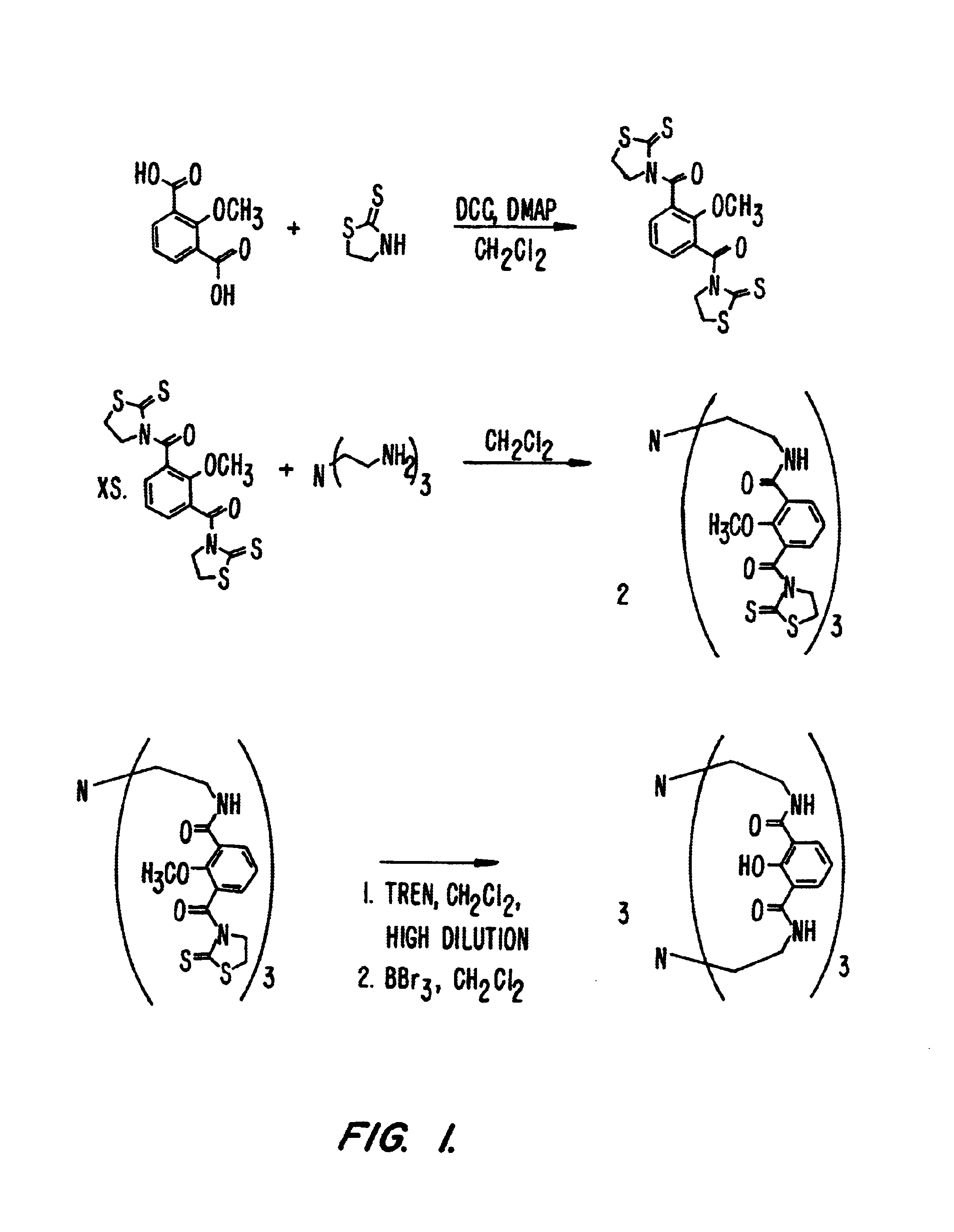
Example 1 illustrates the synthesis of exemplary ligands of the invention and the formation of their metal complexes. The synthetic scheme for the compounds of Example 1 is set forth in FIG. 1.

1.1 Materials and Methods

Unless otherwise noted, starting materials were obtained from commercial suppliers and used without further purification. Flash column chromatography was performed using Merck silica gel 40-70 mesh. Microanalyses were performed by the Microanalytical Services Laboratory, College of Chemistry, University of California, Berkeley. Mass spectra were recorded at the Mass Spectrometry Laboratory, College of Chemistry, University of California, Berkeley. 1H and 13C NMR spectra were recorded on an AMX 300 or AMX 400 Bruker superconducting Fourier transform spectrometer or on a DRX 500 Brucker superconducting digital spectrometer. Infrared spectra were measured using a Nicolet Magna IR 550 Fourier transform spectrometer. The UV / Visible spectra were recorded on a double-beam Per...

example 2

Example 2 details the x-ray structure determination of exemplary compounds of the invention. Molecular models based on the x-ray crystallographic data are set forth in FIG. 4 and FIG. 5.

2.1 X-ray Data Collection, Structure Solutions, and Refinement.

All X-ray structure data sets were collected on a Siemens SMART Area Detector diffractometer (SMART, Area-Detector Software Package; Siemens Industrial Automation, Inc.: Madison, 1994). Crystals were mounted on quartz capillaries in Paratone oil and were cooled in a nitrogen stream on the diffractometer. Peak integrations were performed using Siemens SAINT software package (SAINT, SAX Area-Detector Integration Program v. 4.024; Siemens Industrial Automation, Inc.: Madison, 1994). Space group determinations were done by the software XPREP. The structures were solved by direct methods and refined using the SHELXTL software package (PC version, SHELXTL, Crystal Structure Analysis Determination Package; Siemens Industrial Automation, Inc.: Ma...

example 3

Example 3 details the spectrophotometric titration of exemplary compounds of the invention.

3.1 Spectrophotometric Titrations

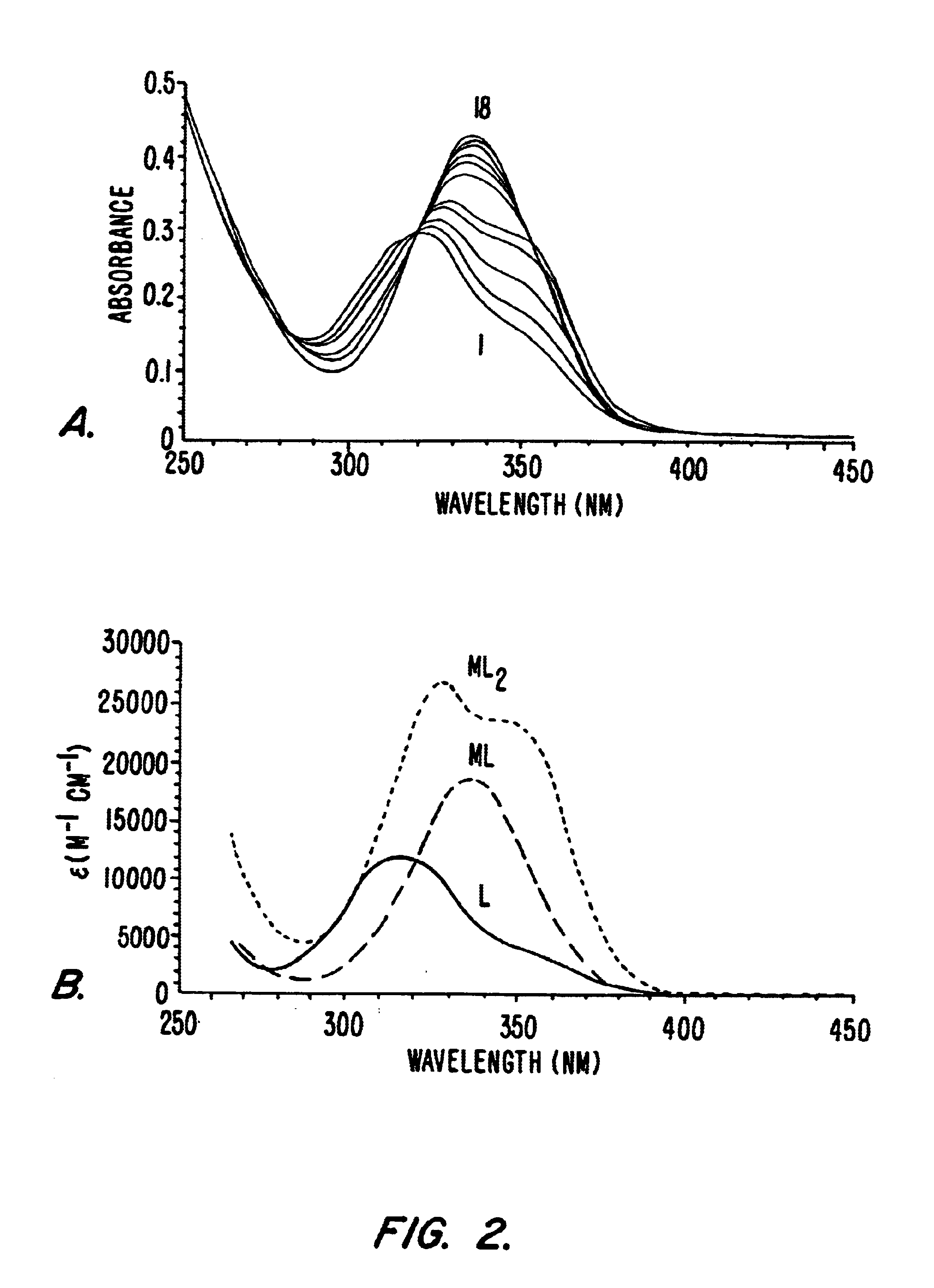
Batch titration samples were prepared in Millipore purified water with MES buffer, 0.1 M KCl, adjusted to pH=5.78 with KOH. The samples were incubated at 37° C. for 15 hours before measurement to ensure thermodynamic equilibrium had been reached. The ligand concentration was 2.32×10⁻⁵ M for all samples and the EuCl3 was titrated from 0 to 2.2 equivalents. The spectra were recorded on a double-beam Perkin-Elmer Lambda 9 UV-Visible spectrophotometer in 1.0 cm quartz Suprasil cell. The samples were kept at a constant temperature of 25.0±0.2° C. using a Neslab RTE-111 water bath. The treatment of the data was performed with the using the software package SPECFIT 2.10.86.1.

3.2 Results

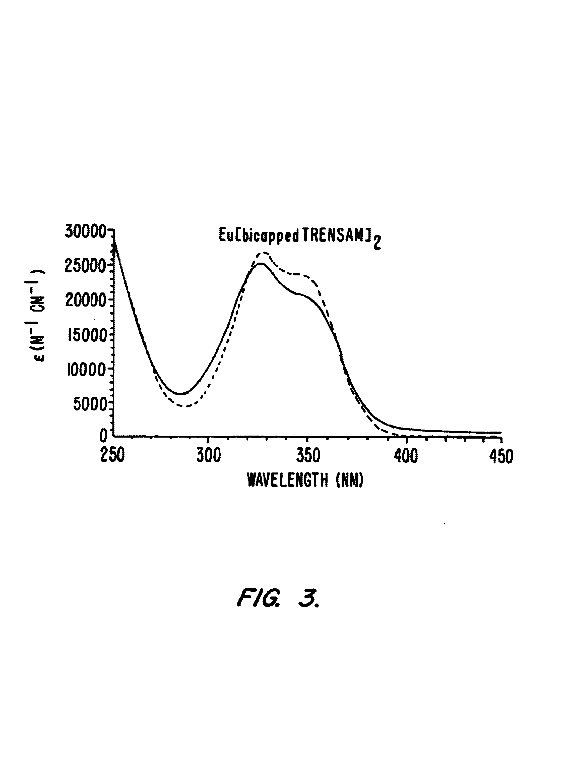
A batch titration of bicapped TRENSAM with Eu3+ was performed in order to evaluate the solution behavior and stability of these complexes. The concentration of the ligand was kept const...


PUM

PropertyMeasurementUnit
molecular weightaaaaaaaaaa
moleclar weightaaaaaaaaaa
molecular weightaaaaaaaaaa

Abstract

The present invention provides luminescent lanthanide metal chelates comprising a metal ion of the lanthanide series and a complexing agent comprising at least one phthalamidyl moiety. Also provided are probes incorporating the phthalamidyl ligands of the invention and methods utilizing the ligands of the invention and probes comprising the ligands of the invention.

Description

BACKGROUND OF THE INVENTIONThere is a continuous and expanding need for rapid, highly specific methods of detecting and quantifying chemical, biochemical and biological substances as analytes in research and diagnostic mixtures. Of particular value are methods for measuring small quantities of nucleic acids, peptides, pharmaceuticals, metabolites, microorganisms and other materials of diagnostic value. Examples of such materials include small molecular bioactive materials (e.g., narcotics and poisons, drugs administered for therapeutic purposes, hormones), pathogenic microorganisms and viruses, antibodies, and enzymes and nucleic acids, particularly those implicated in disease states.The presence of a particular analyte can often be determined by binding methods that exploit the high degree of specificity, which characterizes many biochemical and biological systems. Frequently used methods are based on, for example, antigen-antibody systems, nucleic acid hybridization techniques, an...

Claims


Application Information

Patent Timeline
Patent Type & Authority Patents(United States)
IPC IPC(8): C07C233/00C07D245/04C07D245/00C07F5/00C12Q1/68G01N33/53G01N33/533G01N33/542G01N21/76G01N33/536A61K49/00C07C235/60C07D487/08C07D487/18C07D487/22C09K11/06C12M1/00C12N15/09C12Q1/25G01N33/566G01N37/00
CPCA61K41/0057A61K49/0019A61K49/103A61K49/106A61K49/122A61K49/124A61K51/0478A61K51/0482A61K51/06C07C235/60C07D487/08C07D487/18C07D487/22C09K11/06C12Q1/37G01N33/582A61K49/0002Y10S436/804C09K2211/1007C09K2211/182G01N2458/40Y10S436/80
Inventor RAYMOND, KENNETH N.PETOUD, STEPHANECOHEN, SETH M.XU, JIDE
Owner RGT UNIV OF CALIFORNIA
Learn More