
Materials, method, and apparatus for detecting neutrons and ionizing radiation

a neutron and ionizing radiation technology, applied in the field of polymer scintillator materials, can solve the problems of inability to detect fast neutrons, poor timing resolution, mechanical vibration and shock sensitivity, etc., and achieve the effects of increasing prompt scintillation light output, high solubility of dyes, and high radiation resistan

Inactive Publication Date: 2012-09-27
NANOPTICS
View PDF6 Cites 34 Cited by
  • Summary
  • Abstract
  • Description
  • Claims
  • Application Information

AI Technical Summary

Benefits of technology

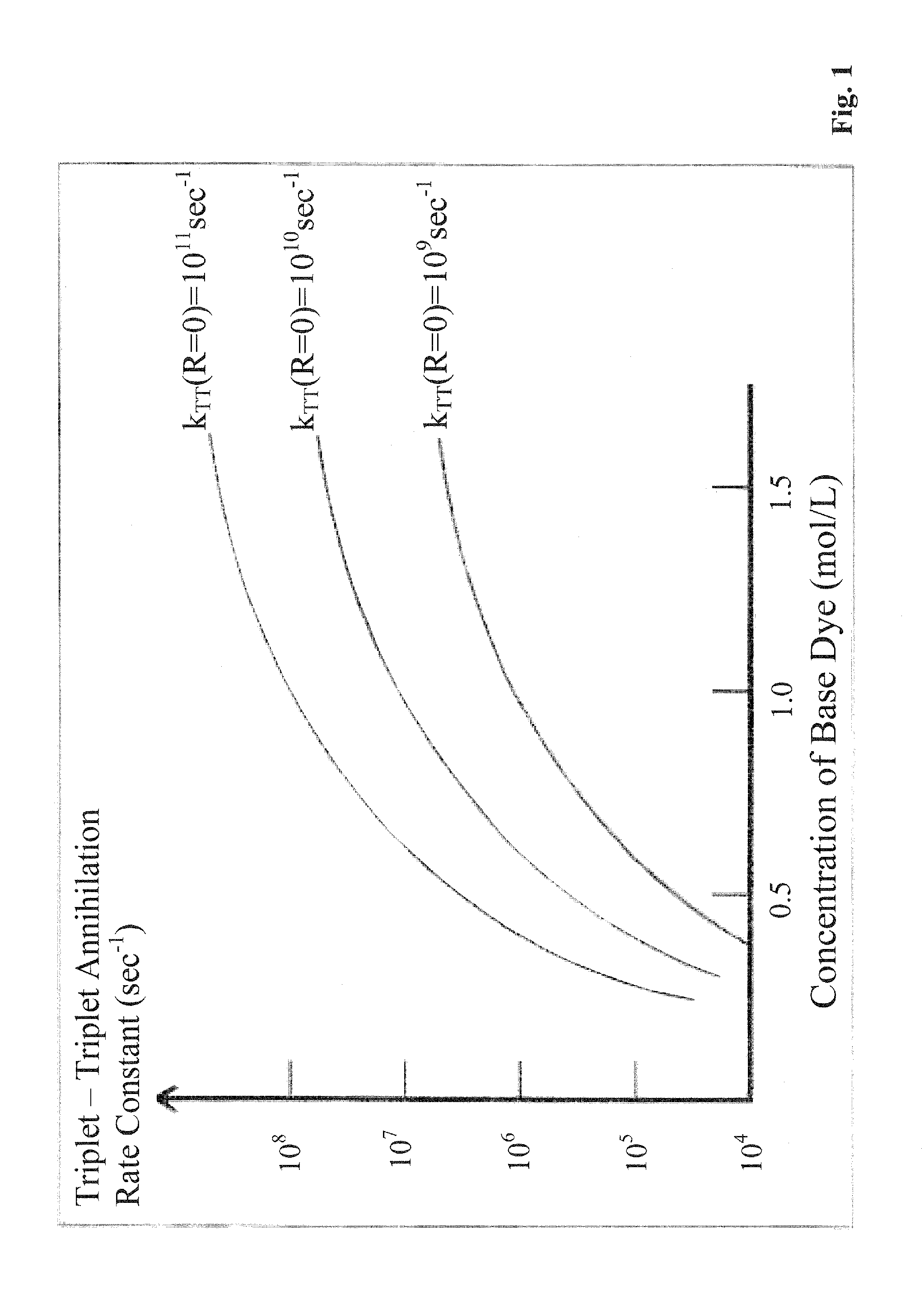
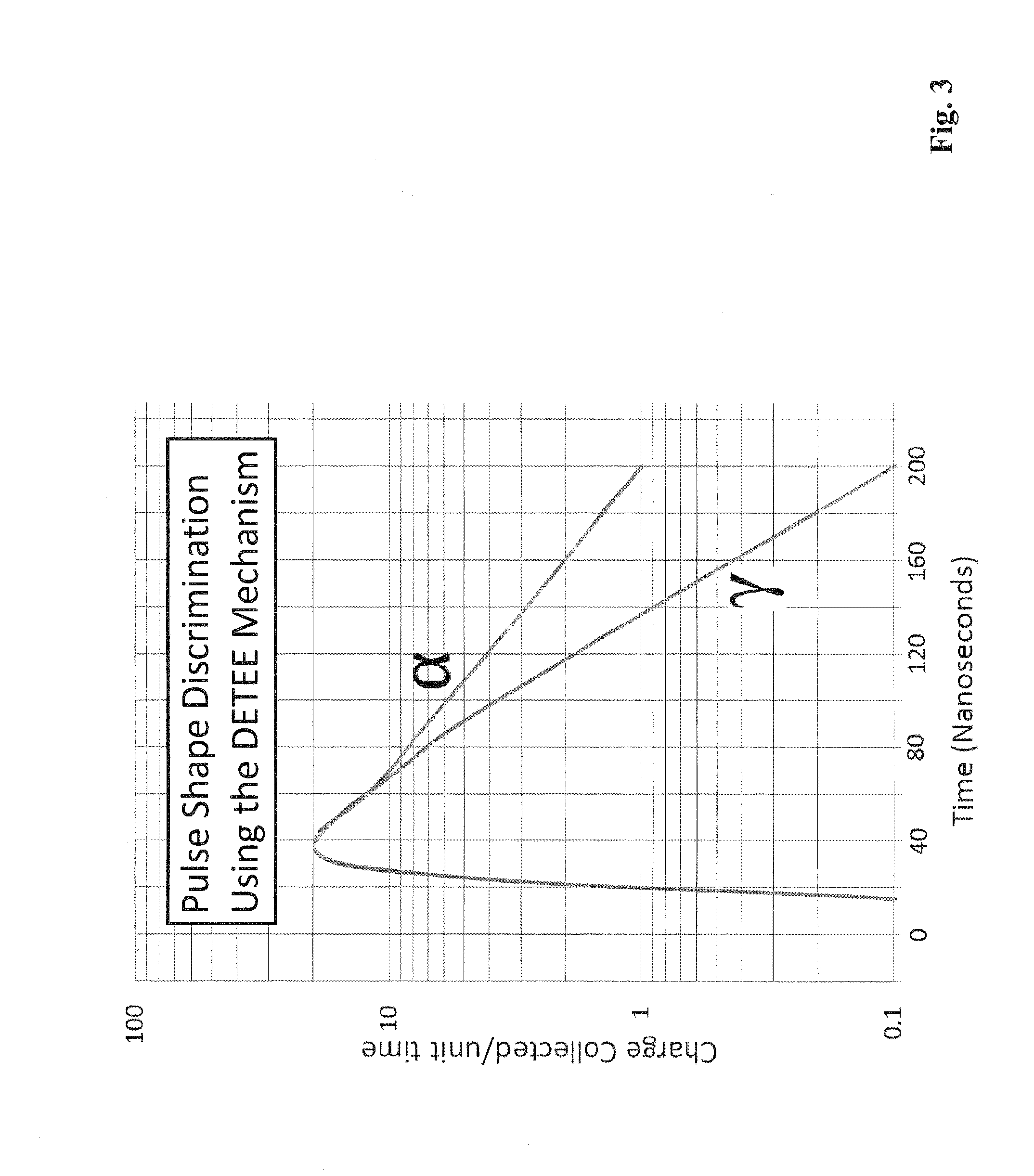
[0019]Embodiments of the invention provide a scintillator comprising a polymer material having one, two, or more, organic dyes dissolved therein. At least one of the dyes, termed the base dye, has a concentration in the range 0.5 to 3.5 mol / L. In a specific embodiment, the base dye has a concentration in the range 1.0 to 3.0 mol / L. This base dye concentration is high enough to achieve a substantial triplet-triplet state annihilation rate despite the negligible diffusion of the dye in the rigid polymer matrix. The rate of triplet-triplet annihilation determines the delayed scintillation time constant. Embodiments of the invention utilize a theoretical model based on Direct Energy Transfer via Electron Exchange (DETEE) between triplet states, which relates base dye concentration to the time constant for delayed scintillation light. The model can be used to aid the design of the material composition of the solid polymeric scintillator. The ability to control the decay time constant of the scintillation light used for PSD is a major advantage of the material composition of specific embodiments of the invention, as compared to the traditional diffusion limited fixed time constant of an organic liquid scintillator.
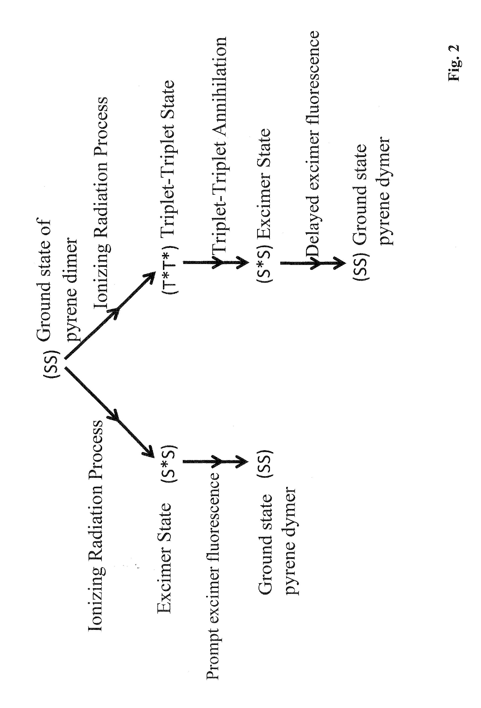
[0020]For tracks with high ionization density along their length, a greater fraction of adjacent triplet states is formed. The annihilation process leads to delayed fluorescence. The combination of prompt and delayed fluorescence provides the PSD. The base dye is selected to have large quantum yield, and can have alkyl substituents, if necessary, to provide increased solubility and quench resistance.
[0025]The scintillating polymer can have a substantially increased prompt scintillation light output, such as by a factor of at least 1.5 and, in certain circumstances, by a factor of more than 2 times that of existing plastic scintillators. Embodiments of the scintillating plastic have a prompt fluorescence lifetime ranging from a few nanoseconds to a few tens of nanoseconds. The selection of the base dye is important to the development of efficient PSD. Embodiments can utilize base dyes having one or more of the following criteria: very high solubility for the dye; high quantum yield and Stokes shift for decay from the first excited singlet state, S1, and several specific properties for the first excited triplet state, T1. A variety of dyes can be used as the primary and secondary dyes. In the above three embodiments, the scintillating plastics exhibit enabling properties for PSD comparable to a liquid scintillator.
[0026]The embodiment having one dye, where the base dye has a large Stokes shift and emitting excimer scintillation light having a wavelength >400 nm, and the embodiment incorporating two dyes, the base dye emitting scintillation light having a wavelength >400 nm and a second dye shifting the wavelength of the light from the base dye further into the visible range, provide a highly radiation resistant plastic scintillator that provides PSD information. In these scintillators, light propagation is designed to occur at wavelengths longer than 400 nm. Because radiation damage to a plastic scintillator produces increased optical absorption at wavelengths less than 400 nm, there is little loss of scintillation light in the material compositions of these two embodiments of the invention.
[0027]In another embodiment of the invention, a single dye is dissolved at a low to moderate concentration in the plastic. This single dye contains two or more chromophores that are held at an optimal distance from each other to create a desirable time constant of the delayed scintillation light. Excimer emission occurs in the form of prompt and delayed fluorescence. The large Stokes shift associated with excimer emission provides good transmission through the plastic scintillator. The combination of prompt and delayed fluorescence light provides PSD information.
[0031]Embodiments of the invention pertain to a scintillating polymeric material that enables efficient PSD and operates reliably in a high radiation field. The plastic can be used to detect fast and thermal neutrons independently of one another. In addition, a fast neutron can be detected, moderated, and detected as a thermal neutron in the capture-gated mode. This new scintillating material composition provides high detection efficiency, while providing excellent gamma rejection for active interrogation.

Problems solved by technology

However, these tubes suffer from some disadvantages, including inability to detect fast neutrons, sensitivity to mechanical vibration and shock, poor timing resolution, and high cost per unit area.
Some of the above disadvantages are also present with respect to another neutron detection technology, namely, lithium loaded zinc sulphide screens read out by plastic optical wavelength shifting fibers.
However, the discrimination against gamma-rays is less than desired in a high background of gamma-rays.
However, there are safety concerns in using large volumes of toxic, flammable, aromatic liquids at port and border locations having high commercial activity and / or utilizing large moving trucks.
The difficulty of growing large crystals makes it unlikely they will be used in anything other than hand-held detectors.
Known as active interrogation, this process creates a relatively high radiation exposure to the container and its surroundings.

Method used


Image

  • Materials, method, and apparatus for detecting neutrons and ionizing radiation
  • Materials, method, and apparatus for detecting neutrons and ionizing radiation
  • Materials, method, and apparatus for detecting neutrons and ionizing radiation

Examples


Embodiment Construction

[0038]Embodiments of the invention provide a scintillator material, a scintillator system, and / or a method of detecting incident radiation using a scintillator material, or scintillator system, comprising a polymer material that comprises chromophores. Additional embodiments provide a scintillator material, scintillator system, and / or a method of detecting incident radiation using a scintillator material, or scintillator system, comprising a polymer material having one, two, three, or more, organic dyes dissolved therein wherein the polymer material having the one, two, three, or more dyes dissolved therein comprises chromophores. At least one of the dyes, termed the base dye, has a concentration in the range 0.5 to 3.5 mol / L. In a specific embodiment, the base dye has a concentration in the range 1.0 to 3.0 mol / L. This base dye concentration is high enough to achieve a substantial triplet-triplet state annihilation rate despite the negligible diffusion of the dye in the rigid polym...


PUM


Abstract

Embodiments of the invention provide a scintillator material, a scintillator system, and / or a method of detecting incident radiation using a scintillator material, or scintillator system, comprising a polymer material that comprises chromophores. Additional embodiments provide a scintillator material, scintillator system, and / or a method of detecting incident radiation using a scintillator material, or scintillator system, comprising a polymer material having one, two, three, or more, organic dyes dissolved therein wherein the polymer material having the one, two, three, or more dyes dissolved therein comprises chromophores. At least one of the dyes, termed the base dye, has a concentration in the range 0.5 to 3.5 mol / L. In a specific embodiment, the base dye has a concentration in the range 1.0 to 3.0 mol / L. This base dye concentration is high enough to achieve a substantial triplet-triplet state annihilation rate despite the negligible diffusion of the dye in the rigid polymer matrix.

Description

CROSS-REFERENCE SECTION[0001]The present application claims the benefit of U.S. Provisional Application Ser. No. 61 / 467,613, filed Mar. 25, 2011, and U.S. Provisional Application Ser. No. 61 / 482,485, filed May 4, 2011, both of which are hereby incorporated by reference herein in their entirety, including any figures, tables, or drawings.TECHNICAL FIELD[0002]Embodiments of the invention relate to polymeric scintillator materials utilized in the detection of radiation. Specific embodiments pertain to polymeric scintillators employed to detect ionizing radiation. Further specific embodiments include a polymeric scintillator material that exhibits pulse shape discrimination for detecting fast and thermal neutrons in the presence of a high gamma ray background.BACKGROUND OF INVENTION[0003]Ionizing radiation energy deposited in a scintillator material is converted into light. This light can then be measured by photo-sensitive detectors. Generally, incident penetrating radiation includes h...

Claims


Application Information

Patent Timeline
IPC IPC(8): G01T1/20C09K11/06G01T3/06
CPCC09K2211/1007C09K2211/1011C09K2211/1029C09K9/02G01T1/203G01T3/06C09K2211/1088G21K4/00C09K11/06C09K2211/10G01T1/2033
Inventor WALKER, JAMES K.NOH, YOUNGWOOKFARLEY, RICHARD T.
Owner NANOPTICS
Learn More