Semiconductor device and manufacturing method thereof
a semiconductor and silicon dioxide technology, applied in the direction of solid-state devices, chemical vapor deposition coatings, coatings, etc., can solve the problems of reducing contact resistance, and reducing the efficiency of silicon dioxide film reforming
- Summary
- Abstract
- Description
- Claims
- Application Information
AI Technical Summary
Benefits of technology
Problems solved by technology
Method used
Image
Examples
first modification
[First Modification]
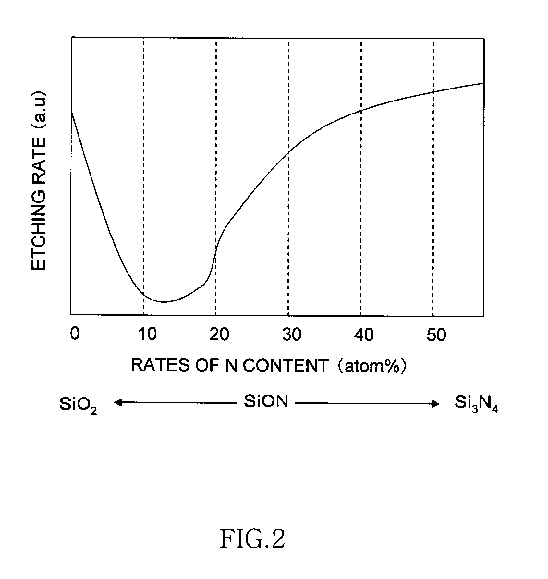
[0071]According to the embodiment described above, in the LPCVD method using the mixed gas including dichlorosilane (SiH2Cl2) ammonia (NH3), and nitrous oxide (N2O), the composition ratios in the SiON films 210, 225, and 241 as the liner films are changed by changing the gas mixing ratio between NH3 and N2O to form the SiON films similar to the oxide film. However, the film forming method of the SiON film is not limited thereto. A modification of the film forming method of the SiON film is explained below.
[0072]FIG. 33 is a time chart for explaining a film forming method of a SiON film according to an ALD (Atomic Layer Deposition) method. As shown in FIG. 33, dichlorosilane (SiH2Cl2), ammonia (NH3), and ozone (O3) are used as film forming gases. In this modification, a pressure in a reaction chamber is constant.
[0073]The ALD method utilizes atom adsorption to a substrate, which is different from the CVD method that enables to produce SiO2 or Si3N4 in a free space...
second modification
[Second Modification]
[0077]FIG. 34 is a time chart for explaining another modification of the film forming method of the SiON film by the ALD method. As shown in FIG. 34, this modification is different from the method shown in FIG. 33 in that a step of vacuuming a reaction chamber is added between each of steps of injecting a film forming gas and each of N2 purging steps.
[0078]According to the film forming method shown in FIG. 34, while film formation time is longer than that in the modification shown in FIG. 33, content rates of Si, O, and N in a SiON film can be more precisely controlled.
third modification
[Third Modification]
[0079]In the embodiment described above, the example in which the coating and steaming of the polysilazane are each performed once to form the silicon dioxide film in the narrow groove-like regions has been described. A method of forming a silicon dioxide film in groove-like regions by using the polysilazane at two steps is explained here.
[0080]FIGS. 35A to 35D and 36A to 36C are schematic cross-sectional views for explaining modifications of a forming method of a silicon dioxide film by using the polysilazane in STI trenches and groove-like regions between gate electrodes, respectively.
[0081]A modification of the forming method of a silicon dioxide film in the STI trenches is explained with reference to FIGS. 35A to 35D. This modification is particularly applied suitably to cases where trenches have greater widths.
[0082]As shown in FIG. 35A, a pad oxide film 302 and a silicon substrate 301 are etched by using a silicon nitride film 303 having openings 304, there...
PUM
| Property | Measurement | Unit |
|---|---|---|
| aspect ratio | aaaaa | aaaaa |
| temperature | aaaaa | aaaaa |
| pressure | aaaaa | aaaaa |
Abstract
Description
Claims
Application Information
 - R&D
- Intellectual Property
- Life Sciences
- Materials
- Tech Scout
- Unparalleled Data Quality
- Higher Quality Content
- 60% Fewer Hallucinations
Browse by: Latest US Patents, China's latest patents, Technical Efficacy Thesaurus, Application Domain, Technology Topic, Popular Technical Reports.
© 2025 PatSnap. All rights reserved.Legal|Privacy policy|Modern Slavery Act Transparency Statement|Sitemap|About US| Contact US: help@patsnap.com


