
Interlocking structure for high temperature electrochemical device and method for making the same

a technology of interlocking structure and electrochemical device, which is applied in the manufacture of final products, cell components, electrochemical generators, etc., can solve the problems that the sintering or chemical bonding between the metal layer and the adjacent ceramic layer is not generally expected, and achieves the effects of improving cell robustness, strong interface, and significant cost reduction

Inactive Publication Date: 2010-06-10
RGT UNIV OF CALIFORNIA
View PDF103 Cites 49 Cited by
  • Summary
  • Abstract
  • Description
  • Claims
  • Application Information

AI Technical Summary

Benefits of technology

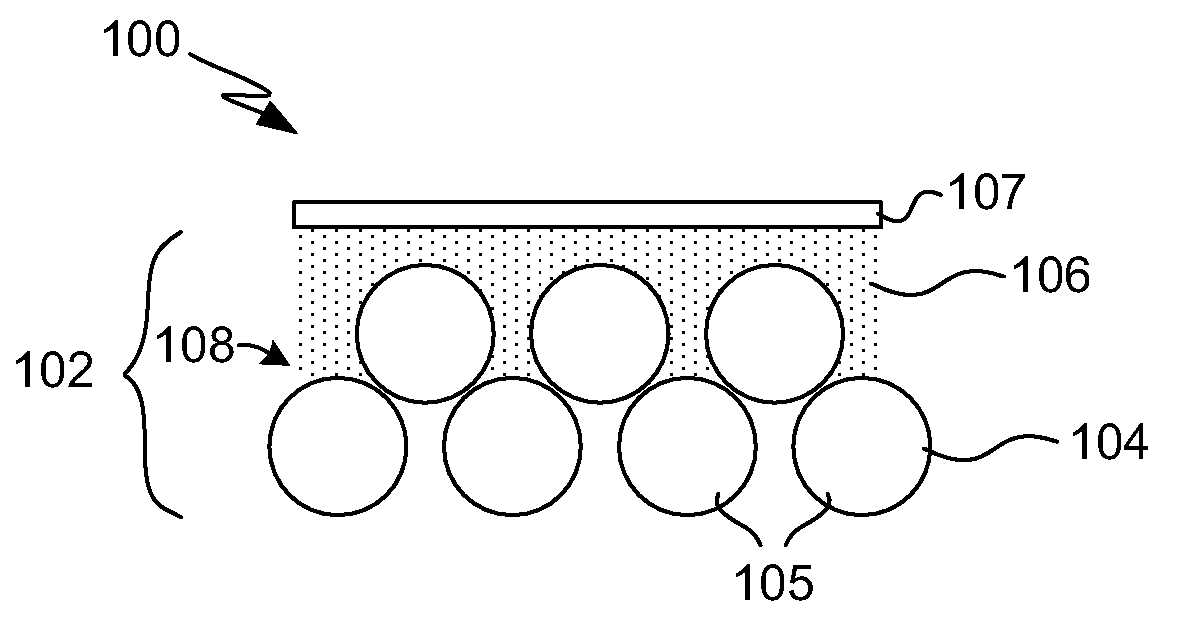
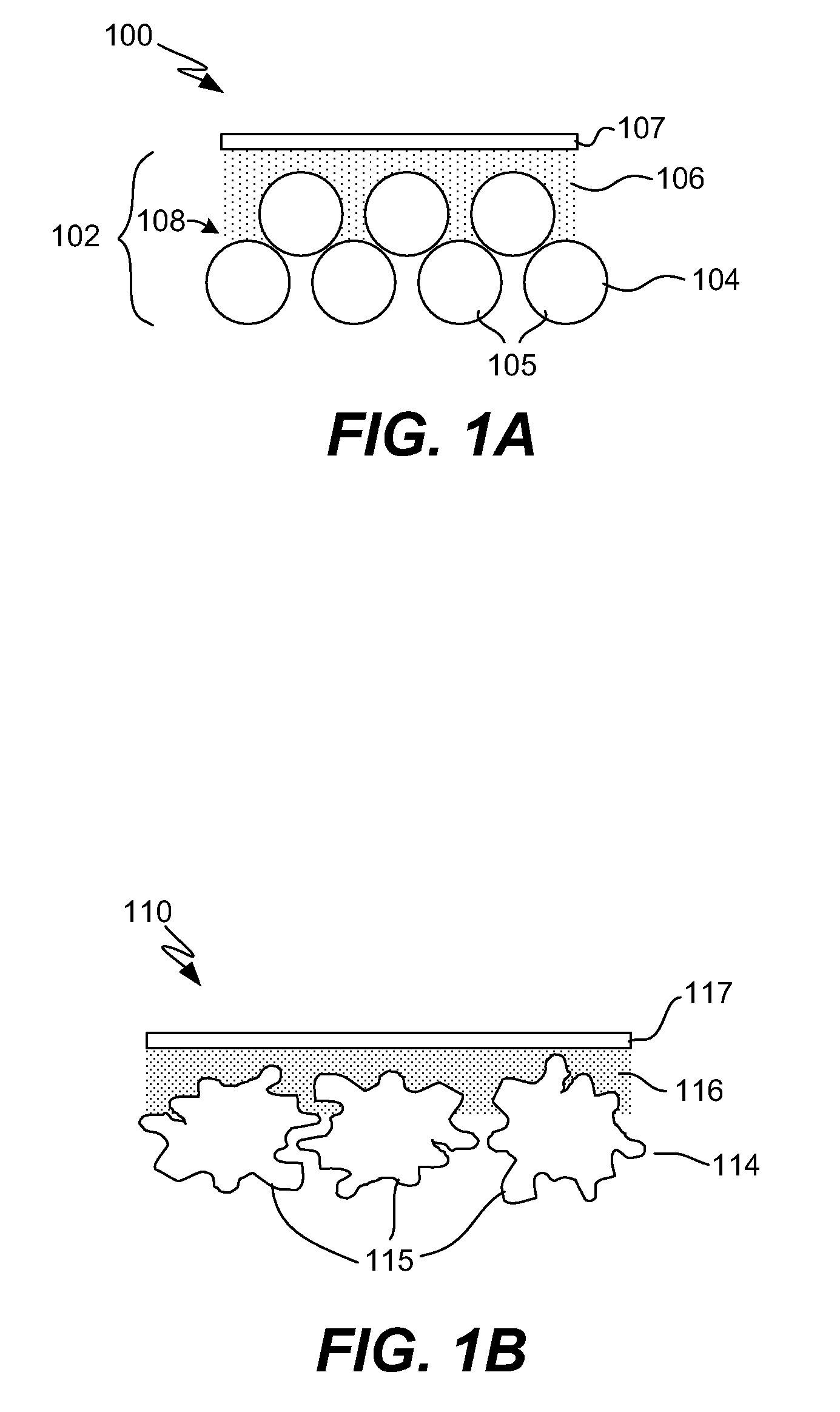
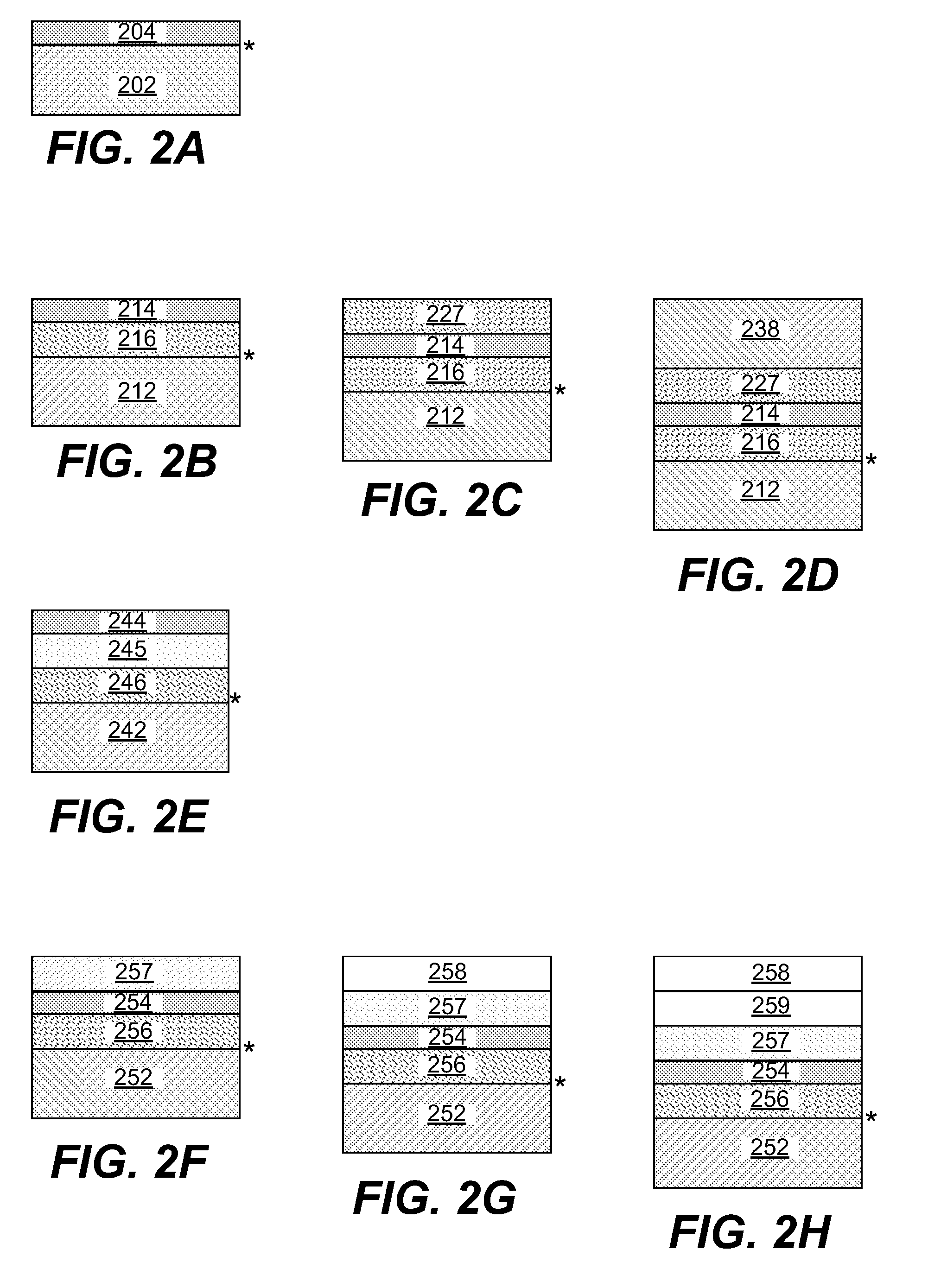
The invention provides a way to prepare high-temperature electrochemical cells using layered structures. These structures consist of a porous ceramic layer with an ionic conductor and a porous metal support or current collector layer. These layers are bonded by mechanical interlocking, which allows for the use of a wider range of catalyst materials and improves cell robustness. The use of a porous metal layer as structural support or current collector layer reduces the cost and allows for a stronger interface between layers. The structures can be used for both planar and tubular cell geometries. The invention also provides a low-cost method of manufacturing the structures by co-sintering the layers. Overall, the invention provides a cost-effective and robust solution for preparing high-temperature electrochemical cells.

Problems solved by technology

However, sintering or chemical bonding between the metal layer and adjacent ceramic layer is not generally expected.

Method used


Image

  • Interlocking structure for high temperature electrochemical device and method for making the same
  • Interlocking structure for high temperature electrochemical device and method for making the same
  • Interlocking structure for high temperature electrochemical device and method for making the same

Examples


example 1

Tubular Structure Comprising Porous Metal / Porous YSZ / Dense YSZ / Porous YSZ / Porous metal

[0077]1. Water-atomized ferritic steel powder (15-75 μm) is mixed with an aqueous dispersion of acrylic (15 wt % solids), polyethylene glycol (PEG) 6000, and polymethyl methacrylate (PMMA) pore former beads (45-106 μm) in the ratio 10:2:0.5:1.5 (metal / acrylic solution / PEG / PMMA). The mixture is heated to remove the water, melt the PEG, and cure the acrylic. The resulting solid mass is ground and sieved to less than 150 μm. This powder is molded in a cold isostatic press to form a green metal support tube.

2. The PEG (which does not volatilize in reducing atmosphere) is extracted by soaking the green support body in water. The acrylic and PMMA remain, and are subsequently removed during bisque firing.

Alternatively, the PEG, PMMA, and acrylic can be removed by firing in air at about 525° C. This temperature is chosen to completely remove the acrylic but not significantly oxidize the metal. This produce...

example 2

Planar Structure Comprising Porous Metal / Porous YSZ / Dense YSZ / Porous YSZ / Porous metal

[0079]The steps are essentially the same as those presented in Example 1 above, however the metal support 510 is a FeCr die-pressed planar substrate. Also, the current collector 518 is applied as a paste [96 wt % metal, 2 wt % YSZ, 2 wt % hydroxypropyl cellulose (HPC) as a binder, enough IPA to make a spreadable paste]. For improved bonding, the metal particles are decorated with YSZ, as described in commonly assigned co-pending application PCT / US2005 / 043109, incorporated herein by reference. The Electrode 1 512, Electrolyte 514 and Electrode 2 516 components are described in Example 1.

[0080]An image of such a structure in cross-section is provided in FIG. 5B.

example 3

Planar or Tubular Structure Comprising Porous Metal / Porous YSZ / Dense YSZ / Porous Ni—YSZ / Optional Porous Metal

[0081]The steps are essentially the same as those presented in Example 1 and 2 above, however the Electrode 2 Interlayer comprises Ni and YSZ. Electrode 2 Interlayer was applied by brush-painting a paint comprising aqueous acrylic (15 wt % acrylic), YSZ powder (such as Tosoh 8YS), Ni powder, 0.5-3.5 μm acrylic pore former bead, and 7-11 μm acrylic pore former bead in the weight ratio 2.7:0.27:0.27:0.2:0.6. Between 5-50 or 7-15 coats are applied, with complete drying between each coat.


PUM

PropertyMeasurementUnit
temperaturesaaaaaaaaaa
thickaaaaaaaaaa
thickaaaaaaaaaa

Abstract

Layered structures and associated fabrication methods that serve as the foundation for preparing high-operating-temperature electrochemical cells have a porous ceramic layer and a porous metal support or current collector layer bonded by mechanical interlocking which is provided by interpenetration of the layers and / or roughness of the metal surface. The porous layers can be infiltrated with catalytic material to produce a functioning electrochemical electrode.

Description

STATEMENT REGARDING FEDERALLY SPONSORED RESEARCH OR DEVELOPMENT[0001]This invention was made with government support under Grant (Contract) No. DE-AC02-05CH11231 awarded by The United States Department of Energy. The government has certain rights to this invention.BACKGROUND OF THE INVENTION[0002]1. Field of the Invention[0003]The present invention pertains generally to the field of solid state electrochemical devices. In particular, the invention relates to structures and associated manufacturing techniques suitable for high temperature electrochemical systems such as solid oxide fuel cells, electrolyzers, and oxygen generators.[0004]2. Description of Related Art[0005]The ceramic materials used in conventional solid state electrochemical device implementations can be expensive to manufacture, difficult to maintain (due to their brittleness) and have inherently high electrical resistance. The resistance may be reduced by operating the devices at high temperatures, typically in exces...

Claims


Application Information

Patent Timeline
Patent Type & Authority Applications(United States)
IPC IPC(8): H01M8/12H01M8/00
CPCH01M4/8657H01M4/8889H01M8/0232Y02E60/525H01M8/1246Y02E60/521H01M8/124Y02E60/50Y02P70/50
Inventor TUCKER, MICHAEL C.LAU, GRACE Y.JACOBSON, CRAIG P.
Owner RGT UNIV OF CALIFORNIA
Learn More