Eureka AIR delivers breakthrough ideas for toughest innovation challenges, trusted by R&D personnel around the world.

System and method for coproduction of activated carbon and steam/electricity

a technology of activated carbon and coproduction, which is applied in the direction of steam use, machines/engines, mechanical equipment, etc., can solve the problems of significant pollution, unoptimized use of separate systems for activation carbon production and energy production, etc., and achieve the effect of reducing nox emissions and increasing heat production

Inactive Publication Date: 2010-05-06
SRINIVASACHAR SRIVATS +3
View PDF6 Cites 14 Cited by
  • Summary
  • Abstract
  • Description
  • Claims
  • Application Information

AI Technical Summary

Benefits of technology

[0021]A fraction of the carbonized product (char) may be introduced into the boiler to increase heat production and / or reduce NOx emissions.

Problems solved by technology

The current use of separate systems for activated carbon production and energy production is not optimal, requires separate energy production for the operation of duplicate processes, and produces significant pollution as a result of the energy production.

Method used


Image

  • System and method for coproduction of activated carbon and steam/electricity
  • System and method for coproduction of activated carbon and steam/electricity
  • System and method for coproduction of activated carbon and steam/electricity

Examples


example 1

Lignite

[0080]A database comprising 1317 as-fired samples of Center lignite was analyzed. The average, standard deviation, maximum, minimum and selected percentiles for ash, sulfur, heating value, and selected ash constituents are included in Table 1.

TABLE 1Statistical analysis of Ash, Sulfur, Heating Value, and Selected Ash Constituents.Ash1S1Heating value2CaO3MgO3K2O3Na2O3B / A4Average9.641.0657813.24.01.34.40.7Standard Deviation2.00.271793.170.80.42.20.34Max25.52.6710124.07.12.313.02.5Min5.00.558526.82.30.20.60.390th Perc.12.511.29682019.95.71.98.71.2610th Perc.7.060.7263599.73.00.62.00.4445th Perc.9.330.90655212.23.81.44.10.5955th Perc.9.750.94659212.74.01.44.60.6450th Perc.9.530.93657212.53.891.44.40.611Weight percent on an as-fired basis.2Heating express as BTU / lb on an as-fired basis.3Weight percent of the ash, elemental weight percent express as equivalent oxide.4B / A is the base to acid ratio of the ash constituents (B / A = [Na2O + MgO + CaO + K2O + FeO] / [SiO2 + Al2O3 + TiO2]).

[...

example 2

Process Flow Parameters

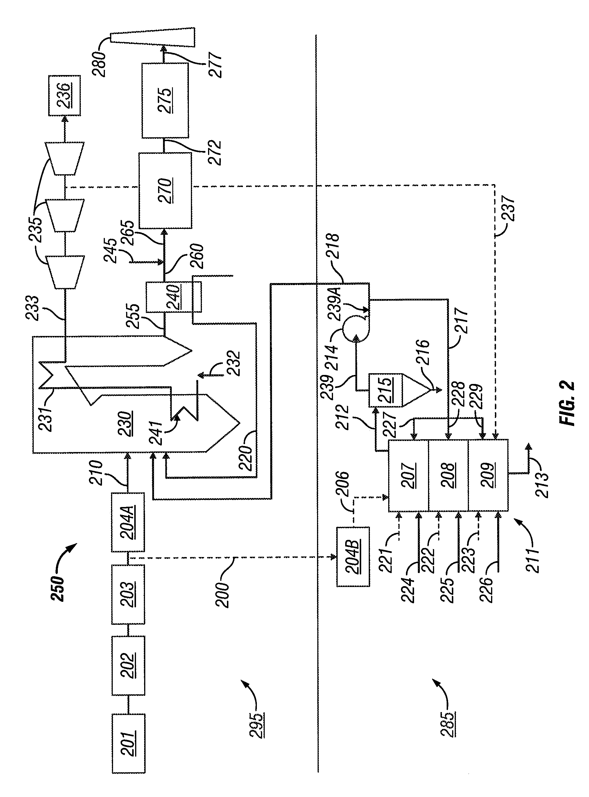
[0082]In embodiments, ACPA 211 of IP 250 comprises a multiple hearth furnace. Flow rates and temperatures of an exemplary process according to an embodiment according to FIG. 2 comprising a MHF are presented in Table 2.

TABLE 2Process Flow ParametersStreamTemp, ° F.lb / hourSCFMACFM200 - Wet coal feed6015700221 + 222 + 223 +601001010227 + 228 + 229Multiple Hearth Furnace(MHF) Fuel224 + 225 + 22660870200200MHF Burner Air +Injection Air2372505000700950MHF Steam212825500001000025000MHF Exhaust Gas238601200025002500Post Combustor Air Supply21316505000Hot Product2341700500001250050000Post Combustor Exhaust Gas

example 3

Carbonization of Biomass, Coal, and Blend of Coal and Biomass

[0083]Production of activated carbon was carried out in a pilot-scale rotary kiln system. Carbonization is first described and steam activation of carbonized char is described thereafter. High potassium sunflower hulls were from a sunflower processing plant in North Dakota, Center lignite coal received from BNI coal. Both sunflower hulls and center lignite coals were sized to nominal −⅛-in. +10-mesh material. A hull and coal blend (HCB) comprising a one to one mass ratio basis of sunflower hull to center lignite coal was carbonized, along with sunflower hull alone and coal alone. Carbonization was performed at 600° C. in the rotary kiln system. The test matrix of the carbonization process is given in Table 3.

TABLE 3Test Matrix for Carbonization Tests in Rotary KilnFeed MaterialCarbonization Temperature, ° C.ReactorSunflower Hull600Rotary kilnCoal600Rotary kilnHull and Coal Blend600Rotary kiln

[0084]The results of the proxim...


PUM

PropertyMeasurementUnit
diameteraaaaaaaaaa
weight percentaaaaaaaaaa
temperatureaaaaaaaaaa

Abstract

A system and method for producing activated carbon comprising carbonizing a solid carbonaceous material in a carbonization zone of an activated carbon production apparatus (ACPA) to yield a carbonized product and carbonization product gases, the carbonization zone comprising carbonaceous material inlet, char outlet and carbonization gas outlet; activating the carbonized product via activation with steam in an activation zone of the ACPA to yield activated carbon and activation product gases, the activation zone comprising activated carbon outlet, activation gas outlet, and activation steam inlet; and utilizing process gas comprising at least a portion of the carbonization product gases or a combustion product thereof; at least a portion of the activation product gases or a combustion product thereof; or a combination thereof in a solid fuel boiler system that burns a solid fuel boiler feed with air to produce boiler-produced steam and flue gas, the boiler upstream of an air heater within a steam / electricity generation plant, said boiler comprising a combustion zone, a boiler-produced steam outlet and at least one flue gas outlet.

Description

CROSS-REFERENCE TO RELATED APPLICATION[0001]This application is a continuation of PCT application PCT / US2008 / 063743, filed on May 15, 2008, which itself claims priority of application 60 / 938,592 filed on May 17, 2007 and application Ser. No. 12 / 120,639 filed on May 14, 2008. The disclosures of these three prior applications are incorporated herein by reference, and priority is claimed.STATEMENT REGARDING FEDERALLY SPONSORED RESEARCH OR DEVELOPMENT[0002]This invention was made with government support under Contract Numbers DE-FC26-98FT40320 and DE-FC26-98FT40321 awarded by the United States Department of Energy. The government has certain rights in this invention.BACKGROUND OF THE INVENTION[0003]1. Field of the Invention[0004]The present invention relates generally to the generation of steam / electricity from a carbonaceous material and the production of activated carbon. Appropriate combination of these two processes provides significant cost savings through requiring fewer pieces of...

Claims


Application Information

Patent Timeline
Patent Type & Authority Applications(United States)
IPC IPC(8): C01B31/08F01K13/00F01K17/00C01B31/10C01B32/336
CPCC01B31/10F01K23/10F01K17/04C01B32/336
Inventor SRINIVASACHAR, SRIVATSBENSON, STEVENCROCKER, CHARLENEMACKENZIE, JILL
Owner SRINIVASACHAR SRIVATS
Why Eureka
Eureka Blog
Learn More