
Method and device for bone regeneration

Inactive Publication Date: 2010-03-25
HACKING ADAM S
View PDF4 Cites 5 Cited by
  • Summary
  • Abstract
  • Description
  • Claims
  • Application Information

AI Technical Summary

Benefits of technology

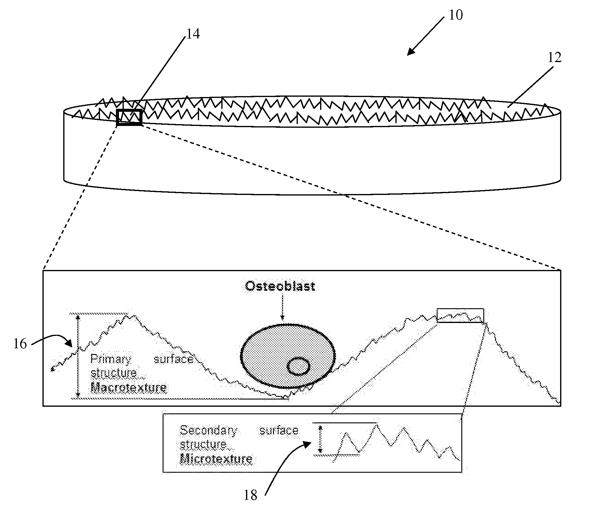
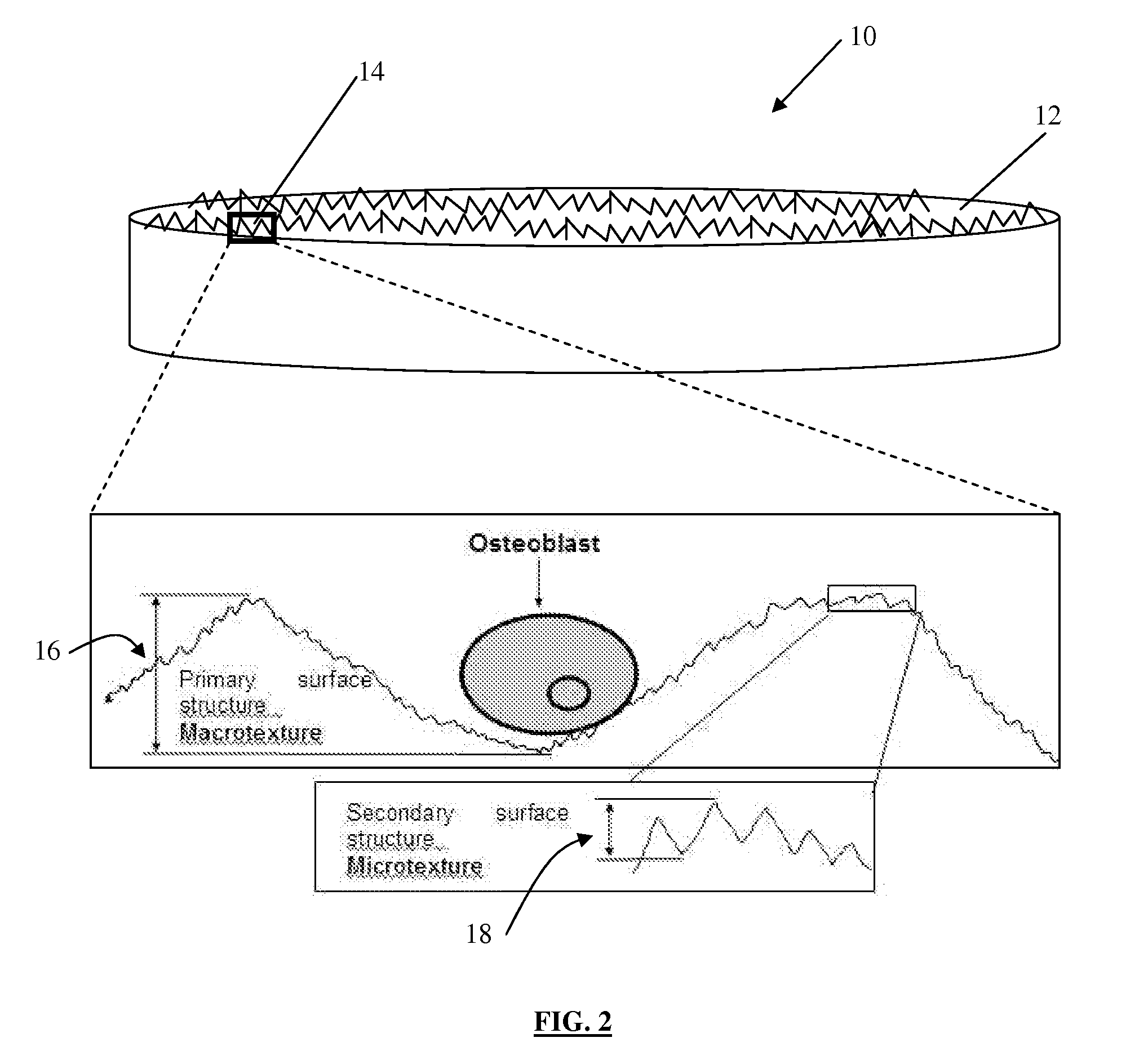
[0009]The present invention reduces the difficulties and disadvantages of the aforesaid designs and treatments. The Inventors made a surprising discovery that some of the physical characteristics (e.g. the roughness (Ra)) of the fracture surfaces of bone are similar regardless of the mode of fracture of the bone, and that such physical characteristics when applied to a bone material can stimulate bone regeneration at that site. The Inventors also surprisingly demonstrated that this bone regeneration was predominantly due to the physical surface characteristics and not primarily as a result of the chemical composition of bone. Thereby, bone material surfaces having some or all of these physical characteristics can be used to treat bone damage such as bone fractures or bone defects. The Inventors have discovered that this can be achieved by adapting a surface of bone material such as by selectively removing bone material from the surface. This is surprising, given the general teaching in the fields of orthopaedics and dentistry which is against the removal of the periosteum (tissue covering bone) or the adaptation of bone surfaces.
[0015]The bone graft of the invention provides an improved rate of attachment to a host bone (faster fusion) by promoting or encouraging bone formation and regeneration to minimize the post-surgery healing period and the stay time in hospital. Also, the bone graft of the invention provide an increased chance of success and a mechanically strong bone with the host bone. Therefore, there is potential for less pain than that provided by bone grafts currently in orthopaedic use.
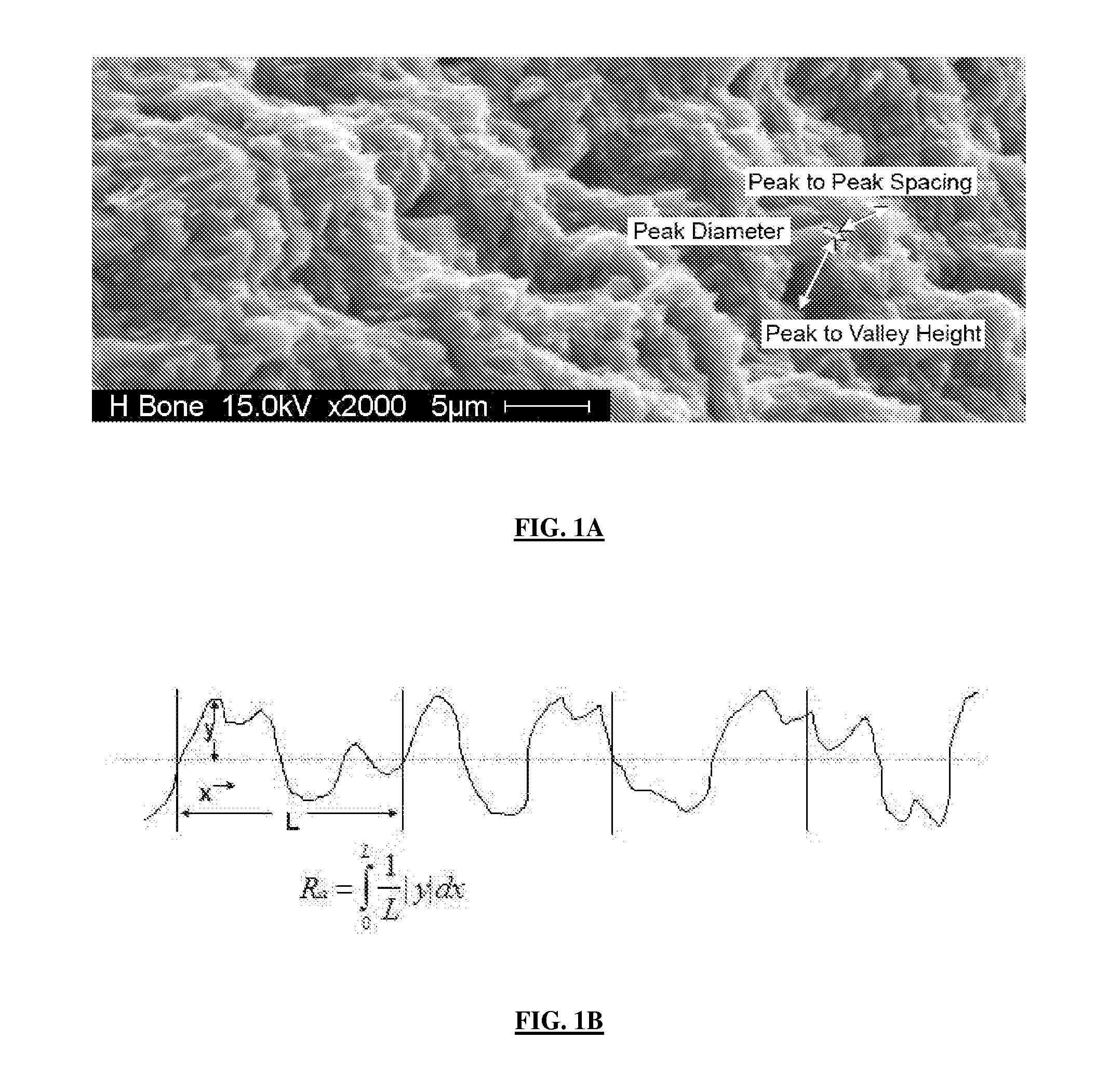
[0016]From yet another aspect, there is provided a method for adapting bone for promoting bone regeneration, the method comprising: accessing at least a portion of a surface of bone to be adapted, the bone comprising bone material; and adapting the surface to produce a surface roughness similar to the roughness of a fracture surface of bone. The bone surface can be adapted by selectively indenting bone material at the surface or selectively removing bone material from the surface. The bone surface can be adapted by mechanically contacting the surface with at least one impacting tip to adapt it. The bone surface is adapted to include macrostructures and microstructures, the macrostructures being peaks and having a peak-to-peak spacing which is substantially less than that of an unfractured bone surface. The peak-to-peak spacing is less than about 180 μm. The roughness, as defined by Ra, is less than about 400 μm. An application of this aspect of this invention is in regard to bone fractures. The bone surfaces near or adjacent the fracture site may be adapted according to the invention. This may be performed to enhance the rate and robustness of the bone healing response or as a prophylactic measure to avoid the chances of non-union or mal-union.
[0019]By means of the invention, the treatment of damaged bone such as bone fracture and defects will be easier and cheaper. For example, the method of the invention provides an adapted bone material surface for promoting bone regeneration which is simple, effective and not damaging to the structural integrity of the bone material itself. Advantageously, the surface can be adapted (textured) without the use of complex apparatus or devices.

Problems solved by technology

Damage to bone can occur through fracture, injury, disease or surgery and may affect any part of the skeletal system.
However, a patient may have a limited supply of bone for graft and autografts can suffer from donor site morbidity.
However, they are less osteoinductive, may induce a greater immunogenic response and suffer from a higher risk of disease transfer compared to autografts.
While these adjuvant therapies increase graft remodeling and new bone formation, they are costly and include risk factors such as osteosarcoma, marrow fibrosis and ectopic bone formation.
The use of bone allografts and xenografts to augment bone healing is expensive and the failure rate is relatively high.
Treatments involving bone grafts often require protracted hospital stays which further increase the associated costs and the burden on the medical system.

Method used


Image

  • Method and device for bone regeneration
  • Method and device for bone regeneration
  • Method and device for bone regeneration

Examples


example 1

Bone Fracture Mode does not Affect Surface Topography

[0077]A fracture model capable of generating commonly observed clinically observed long bone fracture types (butterfly, transverse, comminuted, oblique) was developed to determine the fracture surface morphology for each of these fracture types as well as for periosteal and endosteal bone. Twenty paired femurs from skeletally mature mongrel canines were obtained immediately following euthanasia. Canine femurs are known to approximate human bone physiology, healing and remodelling. The femurs were carefully stripped of soft tissue whilst preserving the periosteum and avoiding damage to the periosteal surface. The harvested femurs were immediately wrapped in saline soaked surgical towels, placed in self-locking bags and frozen at −20° C. until testing. Prior to testing, the paired femurs were thawed at room temperature for 2 hours.

[0078]The proximal and distal ends of each femur were fixed in polymethylmethacrylate (PMMA) to produce...

example 2

Animal Species does not Affect Bone Fracture Surface Topography

[0084]Analysis of the bone fracture surfaces from a number of species (mouse, rat, rabbit and canine) determined that the texture of the fracture surfaces did not vary significantly between species. Transverse fractures were created by placing the bones in a guillotine. The fracture surfaces had a distinct irregular texture (FIG. 10) and were as defined previously in Example 1. The fracture surfaces had an average roughness (Ra) of approximately 2.7-3.3 μm. In contrast, analysis of the endosteal and periosteal bone surfaces revealed a much “smoother” surface with an average roughness Ra of 0.4-0.6 μm (FIG. 11).

example 3

Textured and Fractured Bone Surfaces Promote Osteoblast Mineralization In Vitro

[0085]An in vitro approach was used to assess the response of Canine marrow stromal cells (K9MC) cells to bone disks with surfaces which had been textured so that they were substantially similar to bone fracture surfaces, bone fracture surfaces and polished bone surfaces. Cultures were assessed for proliferation and evidence of mineralization.

[0086]Bone disks Bone disks (FIG. 12) were fabricated from bovine tibia. Bone plugs were cut perpendicular to the tibial shaft using a 21 mm (internal diameter) trephine bit The harvested bone plug was split with an osteotome in the direction of the long axis of the tibia to produce 90 halves each with a fractured surface (Fx bone). Sixty disks were further prepared by petrographic polishing to yield a smooth surface (Pol bone). Thirty of the polished disks were textured in a manner as defined in the present invention. Specifically, a Dremmel™ engraver having a 20 μm...


PUM


Abstract

The invention is directed to a method for adapting a bone graft implantable into a host bone for promoting host bone regeneration, the method comprising providing a bone graft comprising bone material and having a surface contactable with a host bone; and adapting at least a portion of the surface to produce a surface roughness similar to the roughness of a fracture surface of bone. Also included is a bone graft having at least a portion of a bone graft surface with a surface roughness similar to that of a fracture surface of bone, a device for adapting bone material having a plurality of impact tips to contact a surface of the bone material to be adapted to produce a bone material surface roughness similar to the roughness of a fracture surface of bone, and use of a device to adapt a surface of a bone material, the device having an impact tip arranged to contact the surface of the bone material to adapt the surface to produce a surface roughness similar to the roughness of a fracture surface of bone.

Description

CROSS REFERENCE TO RELATED APPLICATIONS[0001]The Applicants hereby claim priority from U.S. patent application No. 60 / 829,340 filed 13 Oct. 2006, the contents of which are hereby incorporated by reference in their entirety.FIELD OF THE INVENTION[0002]The invention relates generally to a method for adapting bone and bone grafts, a bone graft, a device and a use of a device, all for promoting bone regeneration.BACKGROUND OF THE INVENTION[0003]Damage to bone can occur through fracture, injury, disease or surgery and may affect any part of the skeletal system. Bone grafts are often used to assist in the repair or healing of damaged bone, for example in the fields of orthopaedics, maxillo-craniofacial, and periodontics. In cases of non-union or mal-union of bone fractures, for example, one or more bone grafts can be placed around the bone fracture site to promote bone healing. Bone grafting techniques are also used to repair skeletal defects resulting from tumour resection, bone loss ass...

Claims


Application Information

Patent Timeline
IPC IPC(8): A61B17/56A61F2/28
CPCA61F2/28A61F2/30767A61F2/4644A61F2002/4645A61F2002/30925A61F2002/30976A61F2002/2835
Inventor HACKING, ADAM S.HARVEY, EDWARD J.
Owner HACKING ADAM S
Learn More