
Evanescent Field Optical Fiber Devices

a technology of optical fiber and evanescent light, applied in the direction of instruments, heat measurement, optical elements, etc., can solve the problems of increasing the complexity of the step, and the difficulty of manufacturing and us

Inactive Publication Date: 2010-11-25
PHASOPTX INC
View PDF0 Cites 3 Cited by
  • Summary
  • Abstract
  • Description
  • Claims
  • Application Information

AI Technical Summary

Benefits of technology

[0007]The present invention reduces the difficulties and the disadvantages of the prior art by reinforcing an optical fiber itself without, for example, the need of connecting the latter to another optical waveguide.
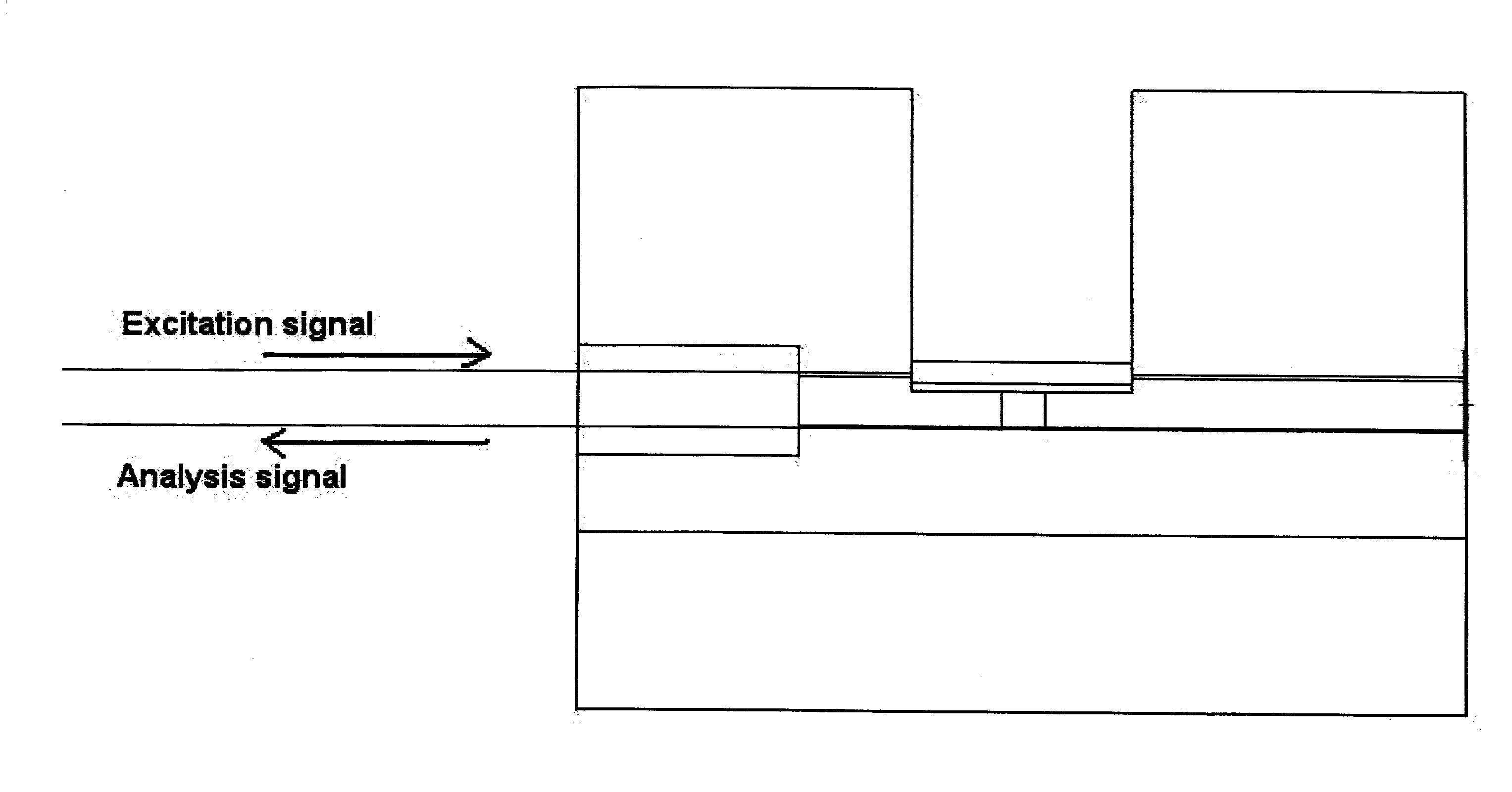
[0008]The present invention relates to an evanescent field optical fiber device comprising one or more optical fibers wherein a portion of said one or more fibers is without coating, and a support which provides for the mechanical integrity of the one or more optical fiber and for access of the evanescent field without impairing the optical fiber.
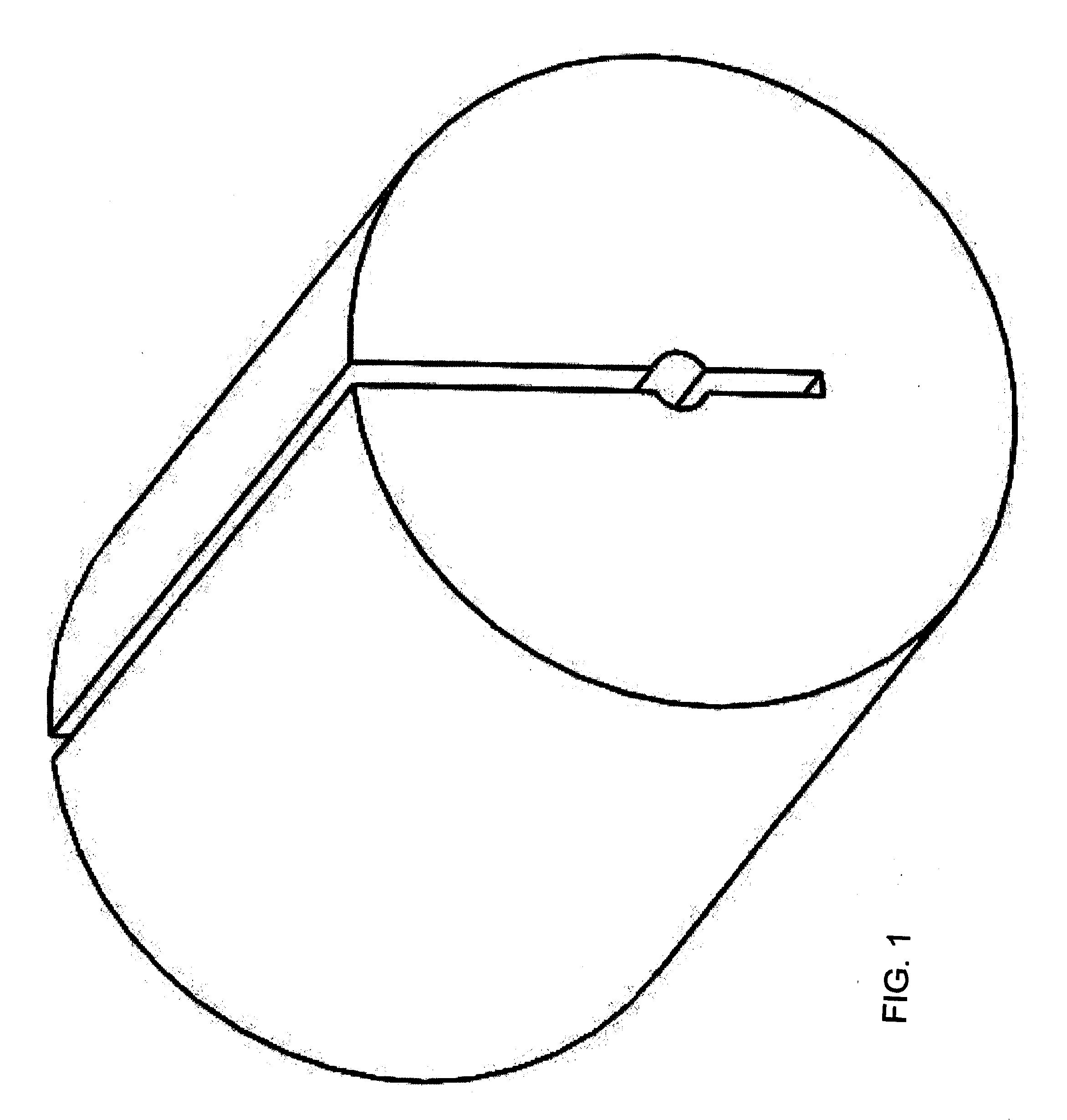
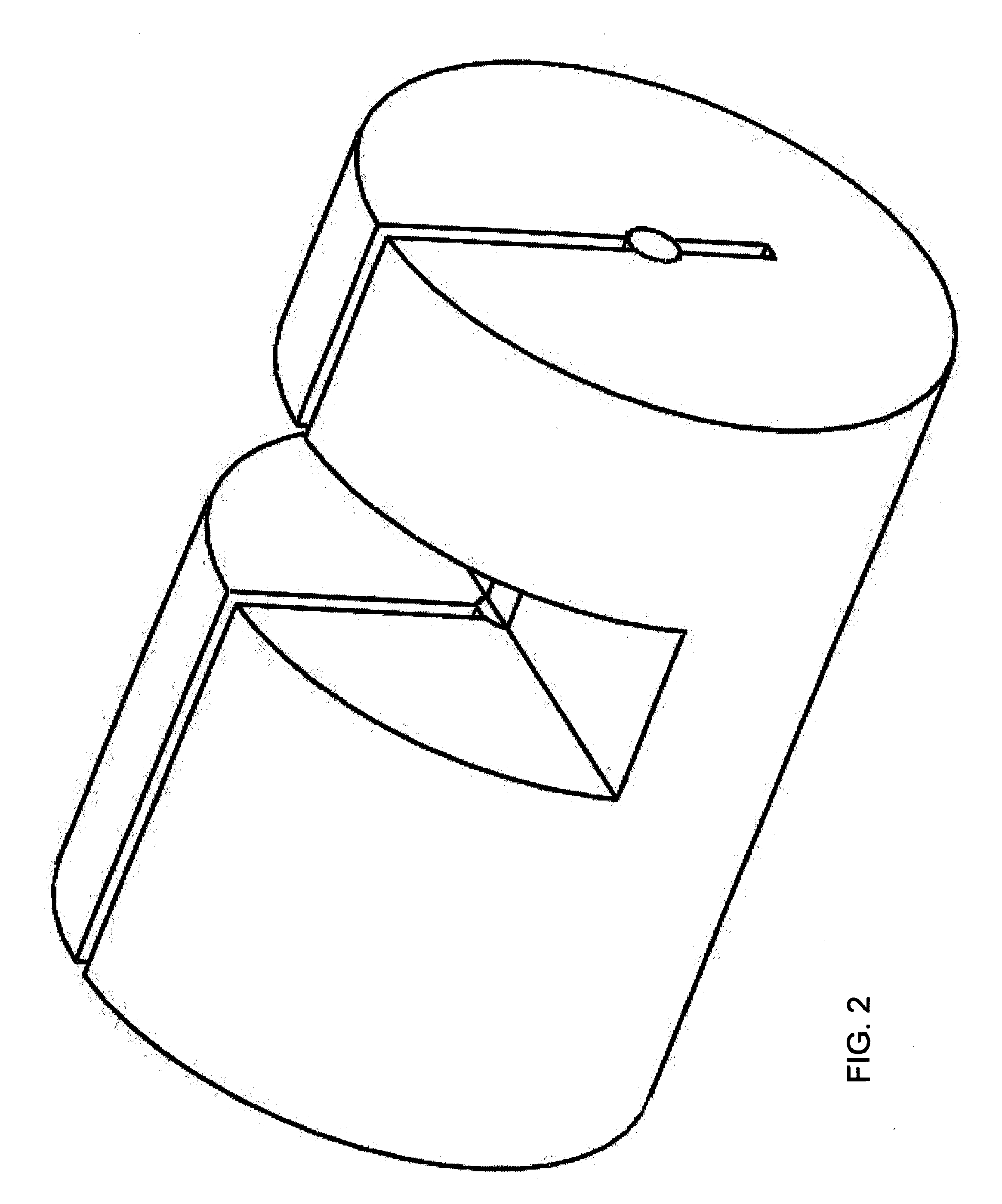
[0009]More particularly, the present invention provides an evanescence based optical fiber device comprising one or more optical fibers as above and a support which assures mechanical strength of the optical fiber wherein one or more grooves has been machined in the support and in a cladding portion of the one or more optical fibers in order to gain access to the evanescent field.

Problems solved by technology

However, when a portion of the cladding of an optical fiber is removed to access the evanescent field, the fiber already of minute diameter is increasingly more fragile and delicate.
Although the third technique may be carried out in very specialized circumstances such as in a laboratory, it is very difficult to manufacture and difficult to use.
This step is not only complex but also requires very precise alignment in order to minimize the loss of light energy.

Method used


Image

  • Evanescent Field Optical Fiber Devices
  • Evanescent Field Optical Fiber Devices
  • Evanescent Field Optical Fiber Devices

Examples


Embodiment Construction

[0029]The present invention is based on a particular use of devices as a support for optical fibers in optical fiber devices, such as optical fiber sensors, couplers, splitters, repeaters, switchers, amplifiers, attenuators, isolators and the like. Such devices are of the type as described in U.S. Patent Nos. 7,066,656 and 7,121,731, and WO 2005 / 040876 published May 6, 2005. A skilled person would understand that the optical fiber will generally comprises at least one core, a cladding and a protective coating layer. For simplicity, we refer herein to cladding only, but it will be understood that when discussing the removal of cladding for the purpose of practicing the present invention, this will include the removal of any other coating on an optical fiber, as may be necessary.

[0030]The present invention is herein described in more detail in an embodiment relating to optical fiber sensors, although a skilled person will readily appreciate and be able to put into practice other embod...


PUM


Abstract

The present invention is directed to an evanescent field optical fiber device including one or more optical fibers and a support which assures mechanical strength of the optical fiber wherein one or more grooves has been machined in the support and in the coating of the one or more optical fiber in order to gain access to the evanescent field. The invention is also directed to the use of a support in the mechanical and chemical removal of coating from an optical fiber and a method of gaining access to the evanescent field of an optical fiber device.

Description

FIELD OF THE INVENTION[0001]The present invention relates to evanescent field optical fiber devices, including optical fiber sensors.BACKGROUND OF THE INVENTION[0002]Evanescence based fiber optic sensors have received considerable attention in the past years due to their widespread applications in various parameter measurements such as temperatures, pressures and of biological and chemical materials that may be present in an environment or sample of interest.[0003]Various techniques, well known in the art, have been developed to access the evanescent field in an optical fiber. For example, an optical fiber may be tapered by stretching it while it is heated, e.g. over a flame. Another technique is by polished coupler in a glass block to protect the optical fiber during the grinding and polishing steps. A third technique entails removal of a portion of the cladding by mechanical or chemical means. However, when a portion of the cladding of an optical fiber is removed to access the eva...

Claims


Application Information

Patent Timeline
IPC IPC(8): G02B6/00G02B6/26
CPCG01K11/3206G01N21/553G02B6/2826G02B6/2821G01N21/7703
Inventor WEYNANT, ERICFRASER, ALEX
Owner PHASOPTX INC
Learn More