
Methods of treating hardbanded joints of pipe using friction stir processing

a technology of friction stir and hardbanded joints, which is applied in the direction of manufacturing tools, other domestic objects, non-electric welding apparatus, etc., can solve the problems of brittle primary carbide, high hardness of primary carbide, and high cost of tungsten carbid

Inactive Publication Date: 2010-02-18
SMITH INT INC
View PDF19 Cites 19 Cited by
  • Summary
  • Abstract
  • Description
  • Claims
  • Application Information

AI Technical Summary

Benefits of technology

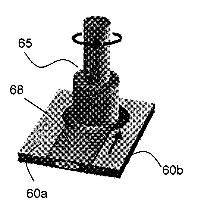
[0015]In another aspect, embodiments disclosed herein relate to a method for improving the properties of a wear reducing material on a tool used in a wellbore operation that includes performing at least one heat treatment on at least a portion of the tool; welding to a surface of the tool a hardfacing alloy using metal gas arc welding; and friction stirring the wear reducing material into the surface of the tool.

Problems solved by technology

Often, these tool joints have a diameter significantly larger than the body of the pipes, thus requiring protection against wear, particularly when drilling through highly abrasive, highly siliceous earth formations.
However, tungsten carbide is expensive, it can act as a cutting tool to cut the well casing in which it runs, and the matrix is a soft steel which erodes away easily to allow the carbide particles to fall away.
Other prior art hardfacing materials used that are harder than siliceous earth materials are brittle and crack in a brittle manner after solidification and upon cooling due to the brittle nature of its structure and the inability of the structure to withstand solidification shrinkage stresses and typically emit sound energy upon cracking as well as causing considerable casing wear as previously stated.
These primary carbides at this high hardness are brittle, have little tensile strength and hence pull apart on cooling from molten state at a frequency that depends on the relative quantity of the primary carbides in the mix of metal and carbide.
Thus, this type of hardfacing material, which is harder than silicious earth materials, when applied by welding or with bulk welding, form shrinkage cracks across the weld bead.
However, there is some limitation on the types of materials that may be used due to limitations of their use with GMAW, GTAW, PTA, and FCAW, as well as limitations on the types of materials which do not harm the casing.

Method used


Image

  • Methods of treating hardbanded joints of pipe using friction stir processing
  • Methods of treating hardbanded joints of pipe using friction stir processing
  • Methods of treating hardbanded joints of pipe using friction stir processing

Examples


Embodiment Construction

[0026]In one aspect, embodiments disclosed herein relate to treatment of hardbands on the surface a tool used in a wellbore operation. In particular, embodiments disclosed herein relate to treatment of a hardband weld using friction stir processing.

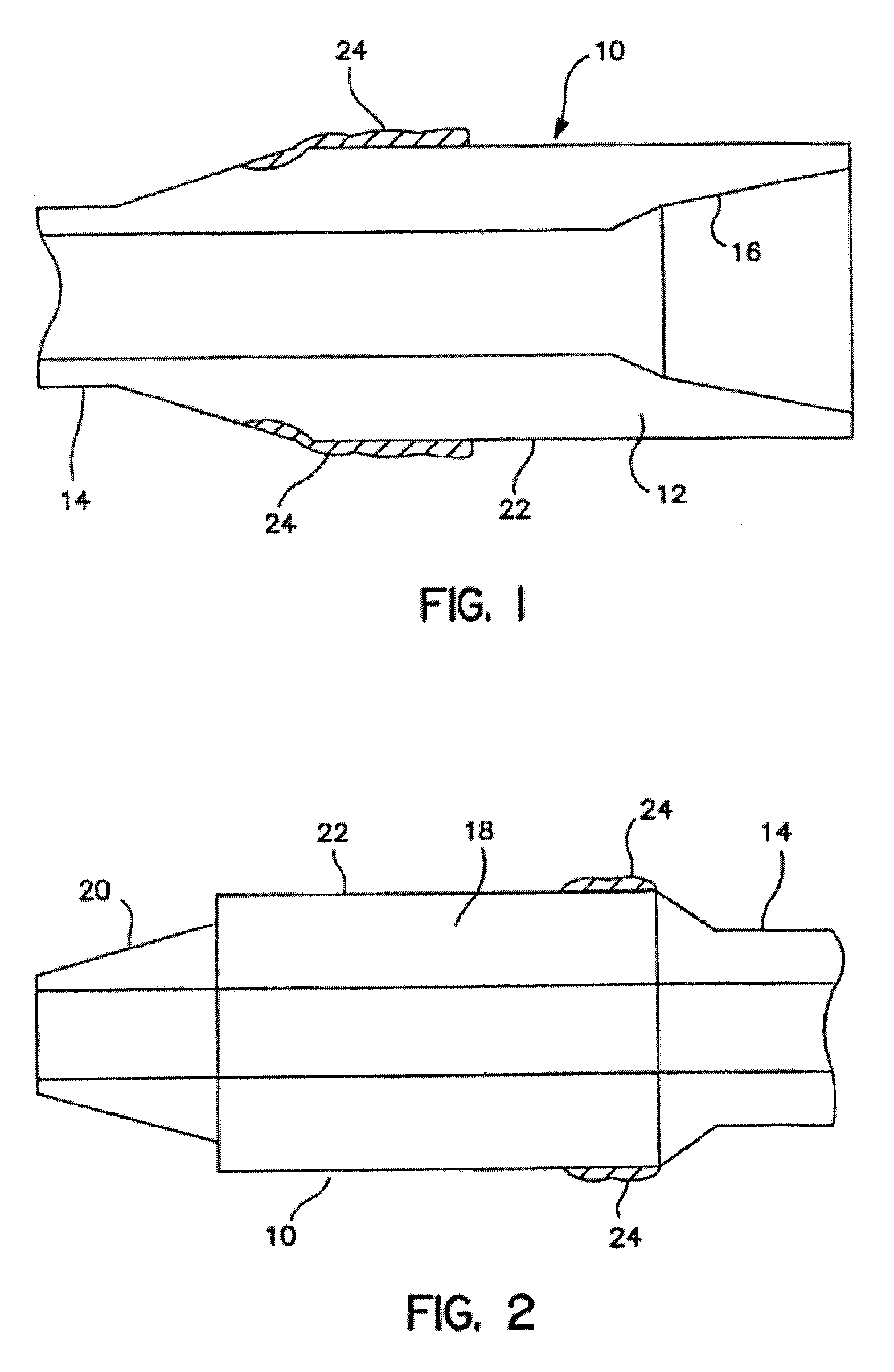
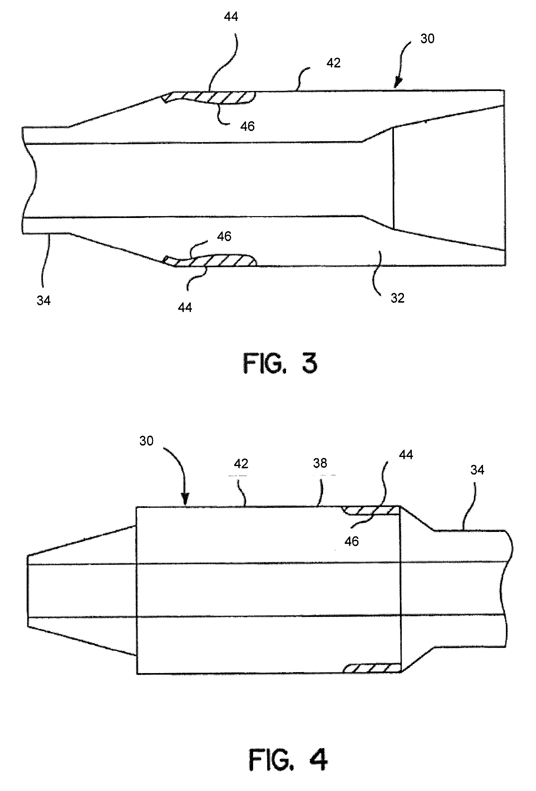
[0027]The methods of the present disclosure may be used to treat a hardband or layer of wear reducing material on any type of tool used in a wellbore operations. However, particular embodiments may relate to use of friction stir processing to treat hardbanding previously applied using other welding techniques on a region of a downhole tool or component having a greater OD than other adjacent components, thus necessitating wear protection for the component. For example, components having a greater OD than other adjacent downhole components may include drill pipe joints, drill collars, stabilizers, etc. However, one skilled in the art would appreciate that the methods of the present disclosure are not so limited, and friction stir processin...


PUM

PropertyMeasurementUnit
lengthaaaaaaaaaa
Brinell hardness numberaaaaaaaaaa
frictional heataaaaaaaaaa

Abstract

A method for treating a wear reducing material welded to a surface of a tool used in a wellbore operation that includes friction stirring the wear reducing material into the surface of the tool is disclosed. Method for improving the properties of a wear reducing material on a tool are also disclosed.

Description

CROSS-REFERENCE TO RELATED APPLICATIONS[0001]This application claims priority, under 35 U.S.C. §119(e), to U.S. Patent Application No. 61 / 088,868, filed on Aug. 14, 2008, the contents of which are herein incorporated by reference in their entirety.BACKGROUND OF INVENTION[0002]1. Field of the Invention[0003]Embodiments disclosed herein relate generally to improved tool joints or other wear surfaces used in wellbore operations. In particular, embodiments disclosed herein relate generally to methods of applying wear resistant materials to and otherwise improving the properties of tool joints or other wear surfaces.[0004]2. Background Art[0005]Drilling wells for hydrocarbon recovery involves the use of drill pipes, to which at one end, a drill bit is connected for drilling through the formation. Rotational movement of the pipe ensures progression of the drilling. Typical pipes may come in sections of about 30 feet in length, and thus, these sections are connected to one another by a too...

Claims


Application Information

Patent Timeline
Patent Type & Authority Applications(United States)
IPC IPC(8): B23K20/12
CPCB23K2201/06B23K20/122B23K20/1275B23K2101/06
Inventor KESHAVAN, MADAPUSI K.STEEL, RUSSELL JROTH, CARY A.ALSUP, SHELTON W.
Owner SMITH INT INC
Learn More