
Antiglare film and display device employing the same, and light diffusing film and surface light source system employing the same

a technology of light diffusing film and display device, which is applied in the direction of instruments, applications, other domestic objects, etc., can solve the problems of poor stability in production and glare phenomenon (speckle) to achieve the effect of improving product yield rate, reducing production costs, and increasing productivity

Inactive Publication Date: 2010-02-11
MITSUBISHI RAYON CO LTD
View PDF0 Cites 9 Cited by
  • Summary
  • Abstract
  • Description
  • Claims
  • Application Information

AI Technical Summary

Benefits of technology

[0036]According to the present invention as described above, by using the roll-shaped die on whose peripheral surface the finely roughened structure was formed as a result of subjecting the peripheral surface of the roll-shaped metallic member to the blasting process, the finely roughened structure is transferred to the surface of the thin film of the active energy ray curing resin composition in order to form the light-transmitting thin film having the finely roughened structure with the arithmetic average inclination angle of 0.5 to 3.5 degrees. Therefore, it is easy to improve the yield rates of products and increase productivity. It is also possible to reduce production costs. Moreover, the antiglare film capable of reducing the occurrence of a glare phenomenon even when the display section emits a beam having high directivity can be provided.
[0037]Moreover, according to the present invention, the following effects are obtained:
[0038](1) With the use of the roll-shaped die, the inexpensive light diffusing films can be continuously produced with high yield rates and high productivity;
[0039](2) Since the evenly, finely roughened structure is formed on the light diffusing film, the light diffusing film with high transparency, no glare and high hiding capability can be produced;
[0040](3) Because of not being sheet production, production costs can be reduced.

Problems solved by technology

(1) If the light diffusing sheet is produced by shape transfer using a resin sheet, this leads to poor stability in production;
(2) If a light source whose directivity is high due to a light deflection element is used, a glare phenomenon (speckle) occurs.

Method used


Image

  • Antiglare film and display device employing the same, and light diffusing film and surface light source system employing the same
  • Antiglare film and display device employing the same, and light diffusing film and surface light source system employing the same
  • Antiglare film and display device employing the same, and light diffusing film and surface light source system employing the same

Examples


example 1

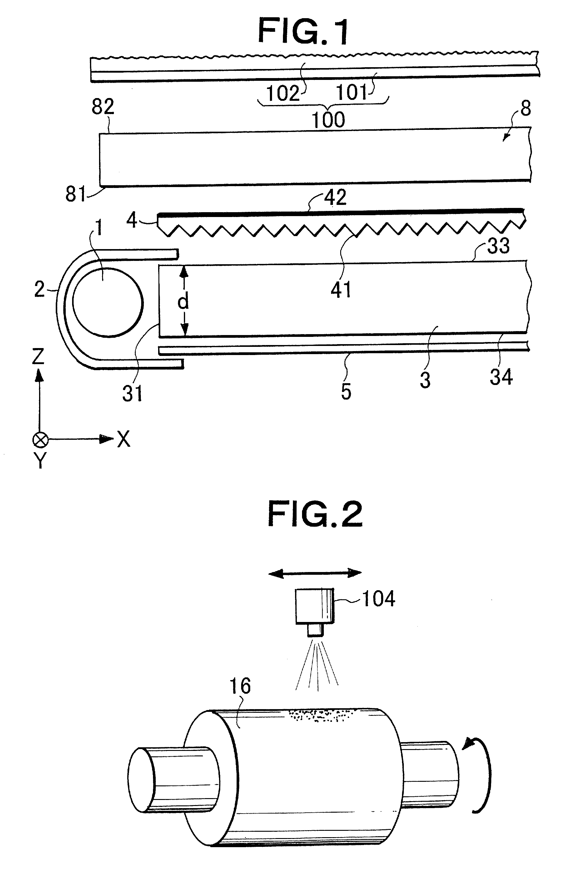
[0140]The peripheral surface of a roll-shaped iron member with a diameter of 200 mm and length of 600 mm was plated with copper so that the thickness of the plated copper was 300 μm, and was then plated with nickel to protect the copper against oxidation. The obtained roll-shaped member was rotated around a rotational shaft with a step of 10 degrees and then stopped. Each time the member was stopped, the blasting process was carried out by discharging the blast particles from the blast nozzle 104 as described above with reference to FIG. 2. In the blasting process, the blast nozzle whose discharge opening had a diameter of 8 mm was disposed 220 mm away from the surface of the roll-shaped member, and discharged a powder of ball-shaped ceramic beads with the mean diameter of 15 to 20 μm and the upper-limit diameter of 21 μm toward the rotational center of the roll-shaped member. The discharging pressure of the blast particles was 0.2 MPa. Therefore, the roll-shaped die whose periphera...

examples 2 to 5

[0154]The finely roughened structure was formed on the peripheral surface of the roll-shaped die, the antiglare film was produced using the ultraviolet curing composition, and the evaluation was carried out in the same way as the above example 1, except that: the blast particles were ball-shaped glass beads whose mean diameter was in the range of 10 to 35 μm and whose upper-limit diameter was 45 μm; and the discharging pressure of the blast particles was 0.3 MPa, 0.4 MPa, 0.5 MPa, and 0.6 MPa, respectively. Table 1 below shows the result.

example 6

[0155]The antiglare film was produced, and the evaluation was carried out in the same way as the above example 1, except that: the blast particles were ball-shaped glass beads whose mean diameter was in the range of 45 to 75 μm and whose upper-limit diameter was 106 μm; and the discharging pressure was 0.4 MPa. Table 1 below shows the result.


PUM

PropertyMeasurementUnit
arithmetic average inclination angleaaaaaaaaaa
diameteraaaaaaaaaa
diameteraaaaaaaaaa

Abstract

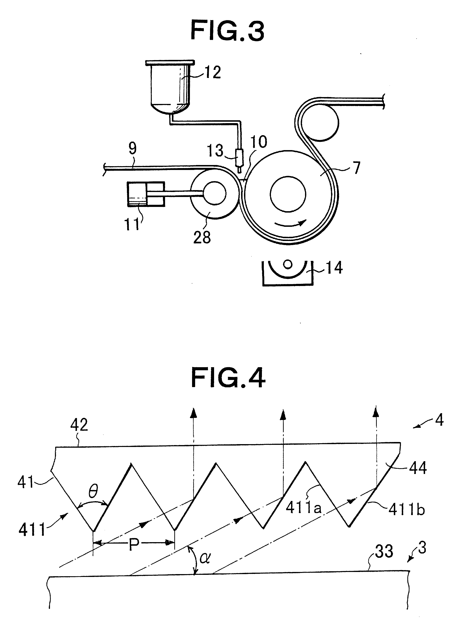
An actinic-energy-ray-curable resin composition (10) is supplied to the nip between a roll-shaped die (7) obtained by subjecting the peripheral surface of a roll-shaped metal member to blasting to thereby form a finely roughened structure and a filmy light-transmitting substrate (9) disposed along the peripheral surface of the roll-shaped die (7), thereby forming the actinic-energy-ray-curable resin composition (10) into a thin film. The finely roughened structure in the peripheral surface of the roll-shaped die (7) is transferred to a surface of the thin film. This actinic-energy-ray-curable resin composition (10) is cured to form a light-transmitting thin film. This film is bonded to the surface of the light-transmitting substrate (9) to obtain an antiglare film. That surface of the light-transmitting thin film which has the finely roughened structure has an arithmetic average inclination angle of 0.5-3.5 degrees.

Description

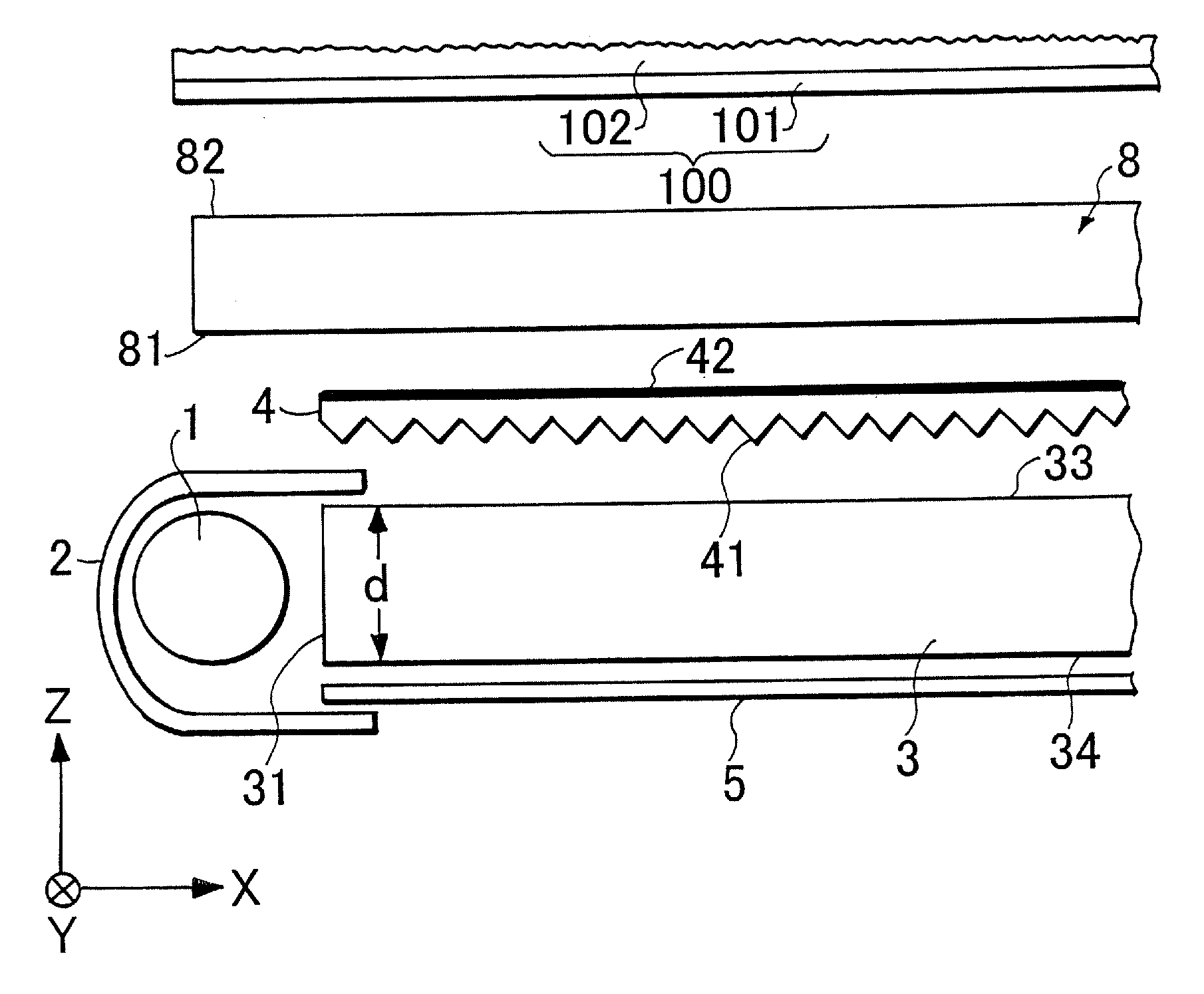
TECHNICAL FIELD[0001]The present invention relates to an antiglare film which is placed on the front of a display surface, such as an image display section of a display device, and which prevents external light from being reflected on the display surface to reduce glare on the display surface and therefore makes it easier to watch an image displayed on the display surface. Moreover, the present invention relates to a display device employing the antiglare film.[0002]Furthermore, the present invention relates to a light diffusing film and its production method. Specifically, the present invention relates to a light diffusing film that are suitable for the construction of a surface light source device which can be used as a backlight of a liquid crystal display device, and a surface light source system employing the film.BACKGROUND ART[0003]Conventionally, for example, as disclosed in JP-B-3515426 (Patent Document 1) or JP-A-2006-154838 (Patent Document 2), as the antiglare film, the ...

Claims


Application Information

Patent Timeline
Patent Type & Authority Applications(United States)
IPC IPC(8): G02F1/13357G02B5/02G02B1/12
CPCG02B1/111G02B5/0221G02B6/0053G02B5/0278G02B5/0294G02B5/0268
Inventor YAMASHITA, TOMOYOSHIOKAMOTO, YOSHIYUKIOOTSUKI, HARUKO
Owner MITSUBISHI RAYON CO LTD
Learn More