B-stage thermal conductive dielectric coated metal-plate and method of making same

Inactive Publication Date: 2010-02-04
THE HONG KONG POLYTECHNIC UNIV
View PDF5 Cites 4 Cited by
  • Summary
  • Abstract
  • Description
  • Claims
  • Application Information

AI Technical Summary

Benefits of technology

[0076]The effect of the coupling agent on the thermal conductivity of the B—N-filled dielectric layer was measured. As depicted in FIG. 9, 1% of the coupling agent was sufficient enough to enhance thermal conductivity, while 2% of the coupling agent resulted in an excessive coating of the filler.
[0077]The effect of the filler content on the dielectric constant with different sizes of B—N-filler was measured, and the results are depicted in FIG. 10A. The results showed that a larger size of B—N filler tended to yield a higher dielectric constant. Also, for a given size of B—N filler, higher B—N filler content also tended to yield a higher dielectric constant. Yet, the overall resultant dielectric constant of the dielectric was kept below 4.5, which is the typical value for PCB materials.
[0078]The effect of the filler content on the dissipation factor with different sizes of B—N-filled dielectric layers was measured, and the results are depicted in FIG. 10B. The results showed a general trend of the dissipation factor decreasing with the increase of filler content. Since the boron nitride filler had a dissipation factor as low as 0.0002, in comparison to that of the epoxy, which was about 0.0327, the filler helped to lower the dissipation factor of the composite.
[0079]Coefficient of thermal expansion (CTE) and glass transition temperature Tg measurements were performed on a Perkin-Elmer thermal mechanical analyser (TMA). These tests complied with the IPC-TM-650 2.4.24C standard method for determining samples mounted on the TMA, which was heated from 23° C. to 175° C. at a he

Problems solved by technology

The potential risks associated with these specific design improvements include an increase in power density and, consequently, a greater risk of thermal problems and failures.
There are many thermal constraints associated with microelectronics and power electronic systems.
At the PCB level, thermal constraints can arise from the thermal conduction of the dielectric material.
This type of thermal conductive dielectric limits the flexibility of PCB design and the fabrication of multi-layer thermal conductive PCBs.
However, the advantage of adding inorganic fillers to a dielectric typically comes with disadvantages in the material properties of the dielectric.
For instance, a dielectric containing an inorganic filler is typically more brittle than the unfilled dielectric.
If the dielectric constant of the material is too high, it may limit the application of the filled dielectric.

Method used


Image

  • B-stage thermal conductive dielectric coated metal-plate and method of making same
  • B-stage thermal conductive dielectric coated metal-plate and method of making same
  • B-stage thermal conductive dielectric coated metal-plate and method of making same

Examples


example 1

Preparation of a B-stage B—N-Filled Thermal Conductive Dielectric Coated Metal-Plate

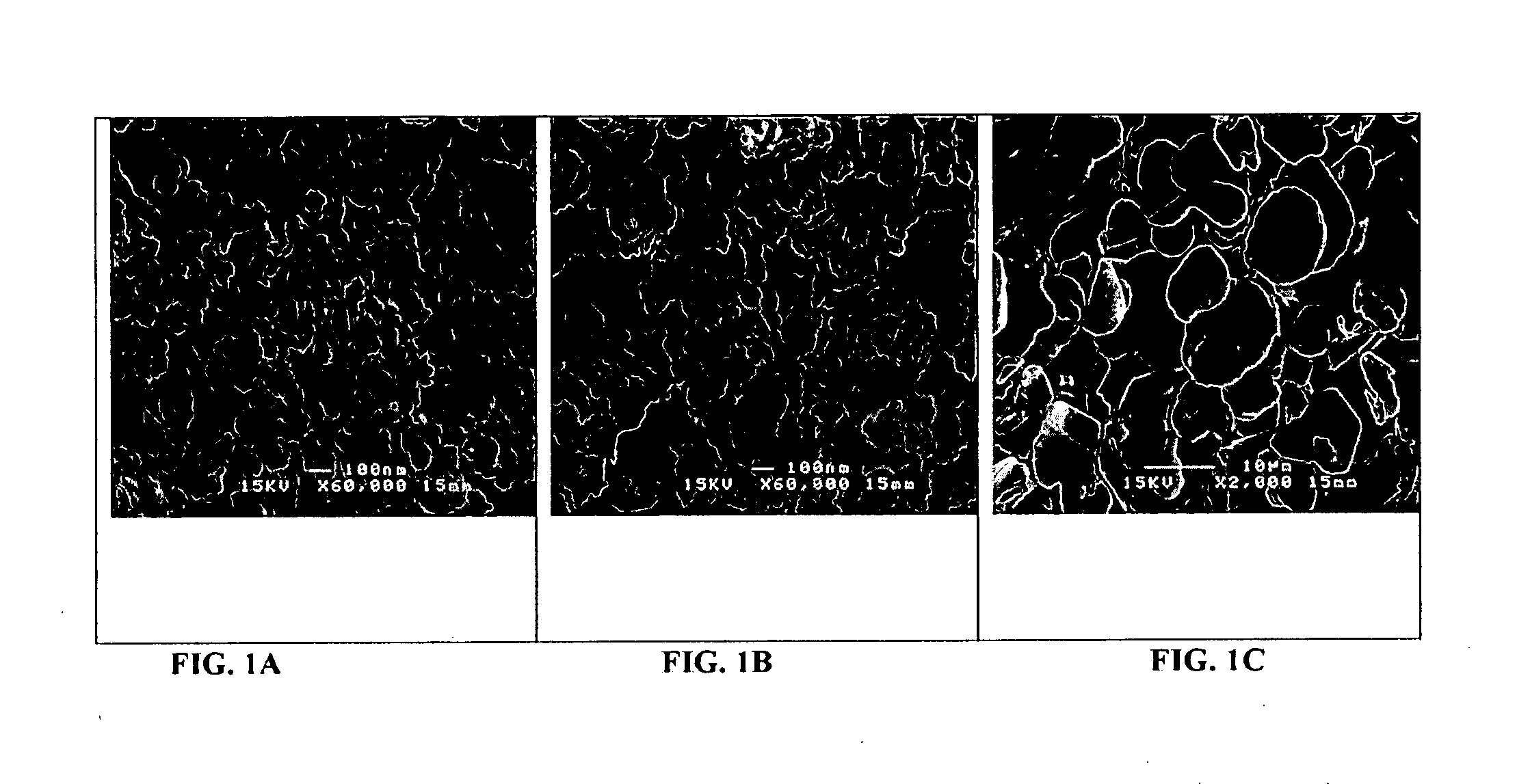
[0066]The following system was chosen for its low viscosity to ensure good dispersion and improved interface between filler and epoxy matrix: brominated difunctional epoxy EP8008 and tetrafunctional epoxy EP1031 (both from Huntsman) were used as epoxy resin components. Dicyandiamide (from Neuto Products) was used as a hardener, and 2-methylimidazole (from Tokyo Kasei Kogyo) was used as an accelerator. Shin-Etsu KBM-403, 3-glycidoxypropyltrimethoxysilane was used as coupling agent. Boron nitride (from Zibo ShineSo and Momentive Performance Materials Quartz) was used as the filler. The B—N filler had a size of either,53 nm, 0.15 μm or 4 μm (AC6004), as depicted in FIGS. 1A to 1C, respectively.

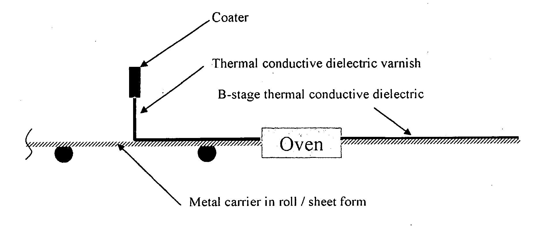
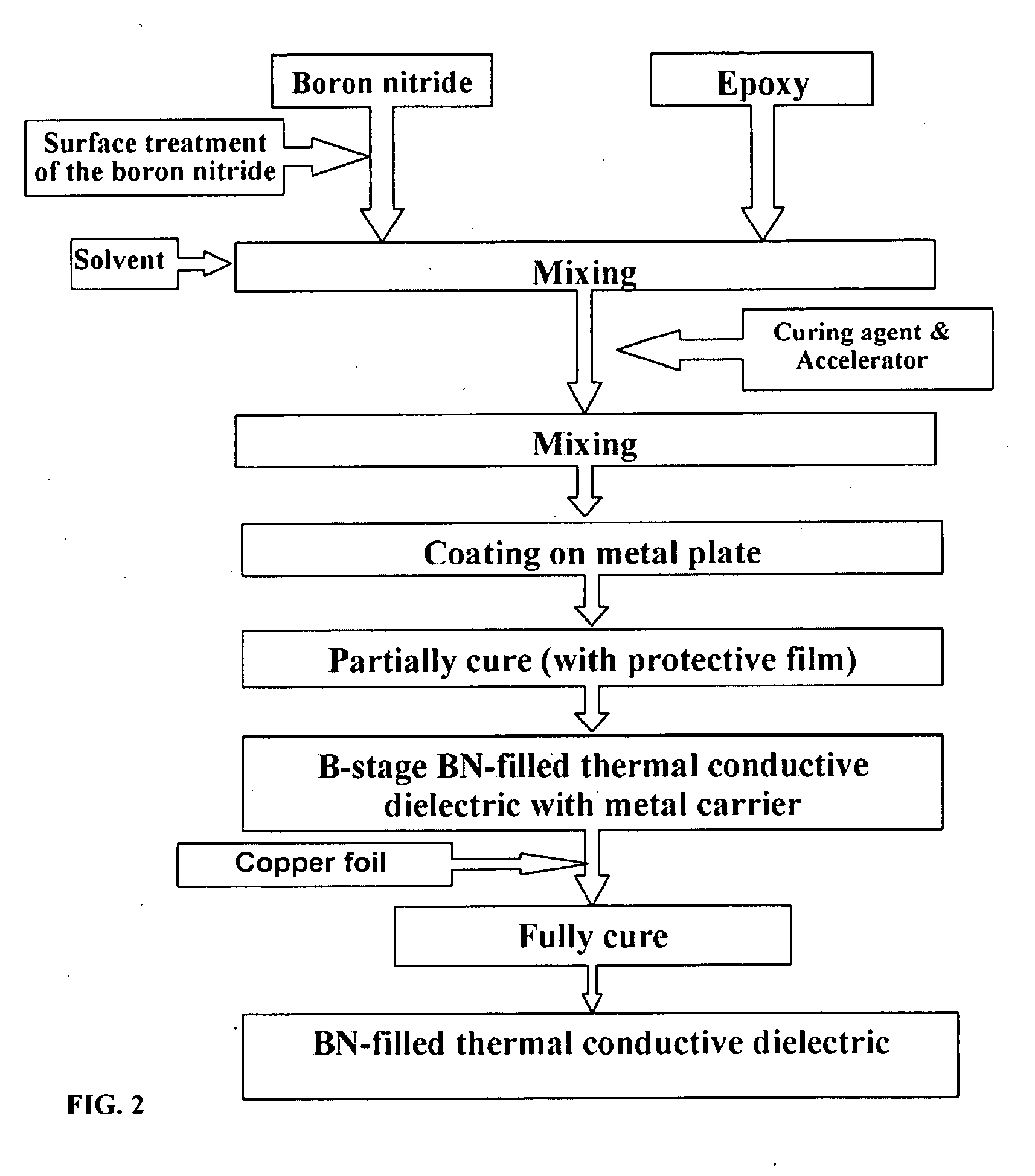
[0067]A process flow for fabricating a B—N-filled thermal conductive dielectric coated metal-plate is depicted in FIG. 2. In this example, the desired volume fraction of boron nitride was mixed with a 1% (with res...

example 2

Preparation of a C-Stage B—N-Filled Thermal Conductive Dielectric Coated Metal-Plate

[0069]In this example, the C-stage B—N-filled thermal conductive dielectric coated metal-plate was fabricated by laminating the B-stage thermal conductive dielectric coated copper foil of Example 1 with another copper foil in a vacuum presser at about 175° C. for about 2.5 hours. The process for preparing a C-stage aluminium nitride-filled dielectric coated metal-plate was the same as that of the boron nitride, except that the boron nitride was replaced with aluminium nitride.

example 3

Thermal Conductivity of B—N Filler-Loaded v. Al—N Filler-Loaded Dielectric Layers

[0070]In this example, the thermal conductivities of the filled thermal conductive dielectric layers of Example 2 were measured. As shown in Table 1, the B—N-filled dielectric layers exhibited higher thermal conductivity than the Al—N-filled dielectric layers for the loadings tested. It was attributed to boron nitride formed thermally conductive networks at lower filler content than aluminium nitride and boron nitride's relatively high inherent thermal conductivity in comparison with aluminium nitride. Consequently, a comparatively low amount of B—N was enough to achieve a high thermal conductivity of the filler-added dielectric layer.

TABLE 1Comparison of thermal conductivity of differentfiller-loaded thermal conductive dielectric layersThermal Conductivity ofThermal Conductivity ofAluminium NitridePercentage of fillerBoron Nitride (W / m-K)(W / m-K)10%0.710.5120%0.710.54Pure filler powders250-300260


PUM

PropertyMeasurementUnit
Percent by massaaaaaaaaaa
Thicknessaaaaaaaaaa
Thicknessaaaaaaaaaa

Abstract

A thermal conductive dielectric coated metal-plate includes a metal carrier, and a partially cured dielectric layer coated to the metal carrier. The dielectric layer includes an epoxy resin, a filler, and a coupling agent.

Description

BACKGROUND[0001]The designs of electronic devices and systems are being continuously improved by becoming smaller in size and faster in communication speed. The potential risks associated with these specific design improvements include an increase in power density and, consequently, a greater risk of thermal problems and failures.[0002]Thermal management requirements also have affected the design of power electronic products, such as motor controllers and drivers, light emitting diodes (LEDs) lighting modules, power supplies and amplifiers, and regulators for televisions. As the demands for denser and faster circuits intensify, the heat dissipation in power electronic printed circuit boards (“PCBs”) is becoming increasingly important. Effective heat dissipation is crucial to enhance the performance and reliability of electronic devices. Materials that are thermally conducting, but electrically insulating, are needed for dielectrics and substrates used in PCBs.[0003]There are many th...

Claims


Application Information

Patent Timeline
IPC IPC(8): B32B15/092
CPCH05K2201/0358C08G59/38H05K2201/0209B05D7/16B05D2504/00B05D2601/20H05K2201/0239C08L63/00C09D163/00H05K1/056H05K3/4655C08L2666/22Y10T428/31529
Inventor YUNG, KAM-CHUENYUE, TAI-MAN
Owner THE HONG KONG POLYTECHNIC UNIV
Why Eureka
Try Eureka