
Microcomputer and motor control system provided therewith

a technology of motor control system and microcomputer, which is applied in the direction of motor/generator/converter stopper, dynamo-electric converter control, instruments, etc., can solve the problems of limited time when the motor can be controlled and low position accuracy, and achieve high accuracy

Inactive Publication Date: 2010-01-14
KK TOSHIBA
View PDF9 Cites 16 Cited by
  • Summary
  • Abstract
  • Description
  • Claims
  • Application Information

AI Technical Summary

Benefits of technology

[0011]Therefore, an object of the present invention is to provide a microcomputer having a function of fast converting an output signal of the resolver without dependence upon software, and a motor control system provided with the microcomputer.
[0013]According to the above-described microcomputer, the position data detected by the resolver can be parallel transferred via an inner bus to a CPU fast since the digital signal converter of the resolver is mounted on the single chip. Furthermore, processing load of the CPU used for signal conversion in JP-A-2005-114442 can be reduced, and a relatively sufficient processing capacity can be distributed to other control. Consequently, a high-accurate motor can be realized.
[0015]According to the above-described motor control system, the motor can be driven with high accuracy when controlled in a high-speed range using the resolver.

Problems solved by technology

However, an angle detected by the Hall element and indicative of a rotor position is coarse such that a position accuracy is low.
This results in a problem that a time when the motor can be controlled is limited except for a period of execution of a position detection processing.

Method used


Image

  • Microcomputer and motor control system provided therewith
  • Microcomputer and motor control system provided therewith
  • Microcomputer and motor control system provided therewith

Examples


Embodiment Construction

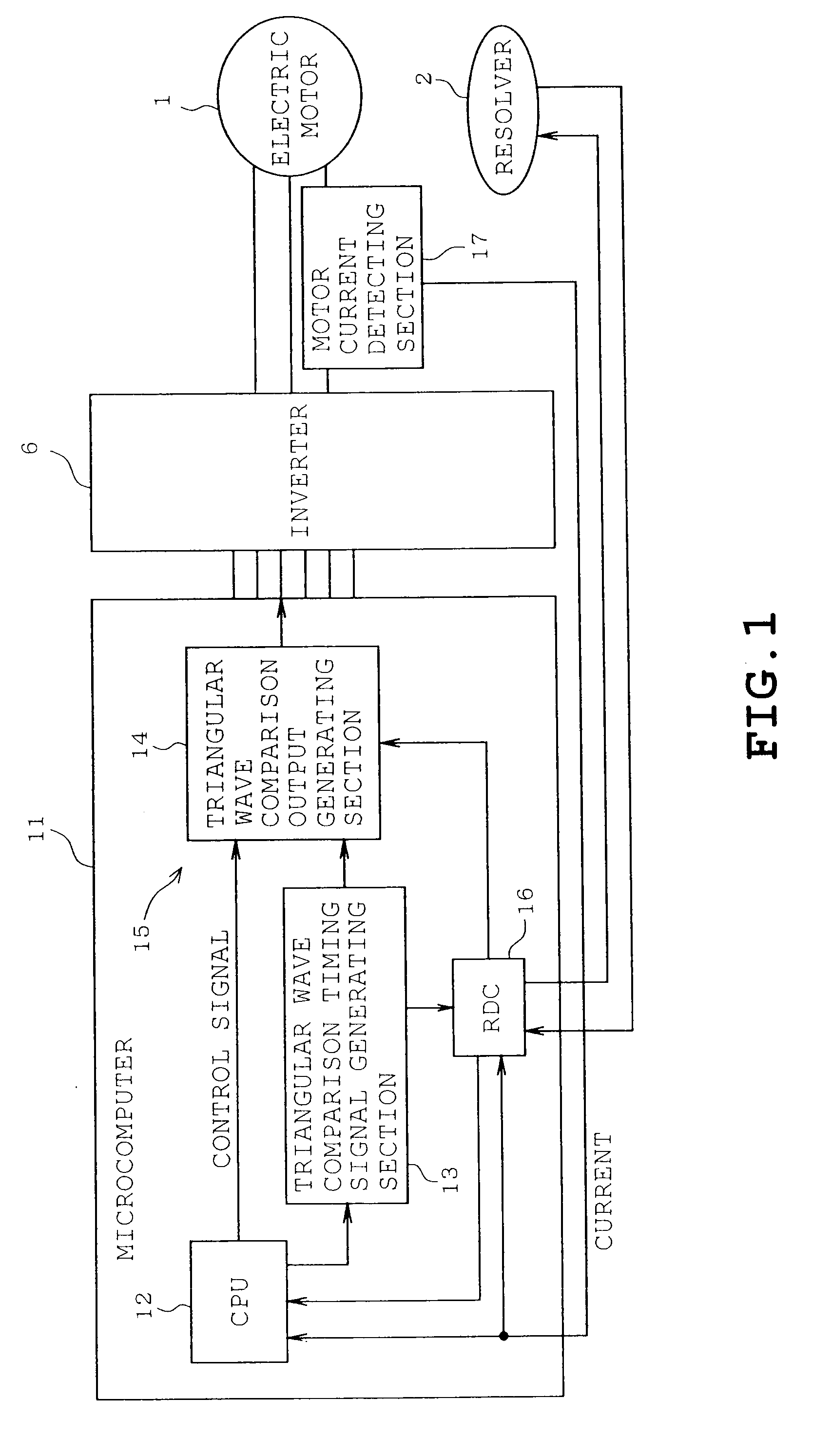
[0021]A first embodiment will be described with reference to FIGS. 1 to 3B. In FIGS. 1 to 3B, identical or similar parts are labeled by the same reference symbols as those in FIG. 5 and the description of these parts is eliminated. Only the differences will be described in the following. A motor control system of the first embodiment comprises a microcomputer 11 (a motor control circuit 11) having a function corresponding to the RDC 3 except for the RDC 3 and the microcomputer 4 as shown in FIG. 5.

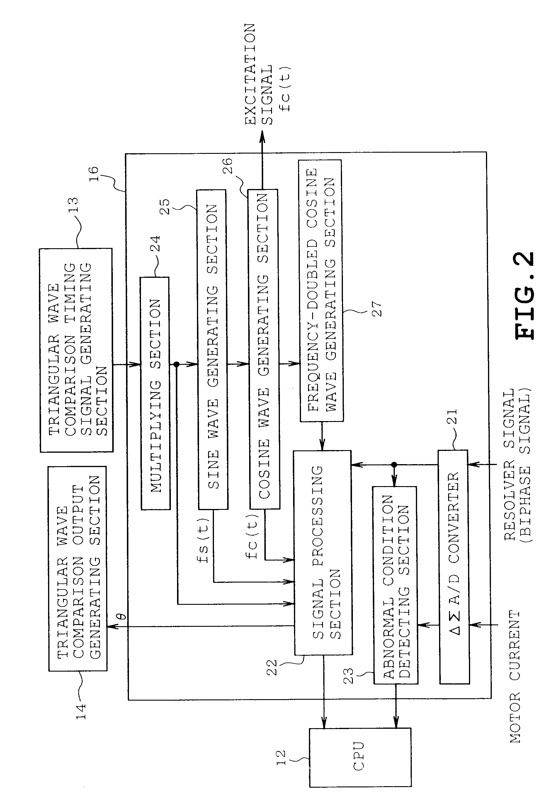
[0022]The microcomputer 11 comprises a single semiconductor chip on which are mounted a pulse-width-modulation (PWM) signal output section 15 composed of a central processing unit (CPU) 12, a triangular wave comparison timing signal generating section 13 (carrier wave output section; and hereinafter, “timing signal generating section”), and a digital signal converter 16 (RDC). Thus, the microcomputer 11 is configured into a one-chip microcomputer. An electric motor 1 may be a spindle motor...


PUM


Abstract

A microcomputer which obtains a rotor position signal from a biphase signal delivered by a resolver mounted on an electric motor according to a rotation phase of a rotor relative to a stator, thereby controlling the motor based on the rotor position signal. The microcomputer includes a digital signal converter which is configured by hardware and converts the biphase signal delivered from the resolver into a digital data position signal, the digital signal converter being mounted on a single chip.

Description

CROSS-REFERENCE TO RELATED APPLICATIONS[0001]This application is based on and claims the benefit of priority from the prior Japanese Patent Application No. 2008-181347, filed on Jul. 11, 2008, the entire contents of which are incorporated herein by reference.BACKGROUND[0002]1. Field[0003]The present invention relates to a microcomputer which obtains a rotor position signal from a biphase signal delivered from a resolver mounted on an electric motor, and a motor control system provided with the microcomputer.[0004]2. Related Art[0005]Low-cost position sensitive detectors such as a Hall element need to be disposed at a predetermined location of an electric motor to detect a rotor position in order that a brushless DC motor may be driven. However, an angle detected by the Hall element and indicative of a rotor position is coarse such that a position accuracy is low. In particular, when the Hall element is used for sinusoidal drive which necessitates a high accurate position detection, ...

Claims


Application Information

Patent Timeline
Patent Type & Authority Applications(United States)
IPC IPC(8): H02P6/16G01D5/245H02P6/06H02P6/08
CPCG01D5/2451H02P6/165G11B19/28H02P6/17
Inventor HASEGAWA, YUKIHISAHARA, TAKEHIRO
Owner KK TOSHIBA
Learn More