
High vacuum suction casting method and apparatus

a vacuum casting and vacuum technology, applied in the direction of casting parameters measurement/indication devices, manufacturing tools,foundry moulding apparatuses, etc., can solve the problems of inferior mechanical and chemical properties of the cast product, gas defects, shrinkage cavity defects, etc., to improve production, the effect of not excessively long time and high vacuum

Inactive Publication Date: 2009-12-31
IE SOLUTION CORP
View PDF1 Cites 4 Cited by
  • Summary
  • Abstract
  • Description
  • Claims
  • Application Information

AI Technical Summary

Benefits of technology

[0062]Various advantages as indicated below are obtained according to the present invention as described above. First, as a result of installing a seal between the die cavity and the feeding tube, a high vacuum can easily be generated inside the die cavity since the die cavity can be depressurized independent of the feeding tube. This is because the locations to be depressurized are minimized, and the die cavity can be depressurized over time in the absence of the molten metal. However, although the timing of depressurization is normally within several seconds, which is longer than the case of ordinary vacuum die casting, the time is not excessively long so as to worsen productivity. In cases in which depressurization time is unavoidably long due to the generation of gas from a coated mold or due to the structure of the die or mold, the die cavity can be depressurized in advance by using a consumable seal as previously described. This is because, since the consumable seal is in the form of a thin plate, it is suctioned against the gate by the decrease in pressure in the die cavity, thereby enabling sealing to be carried out easily. In addition to the entrainment of gas being eliminated as a result of generating a high vacuum in the die cavity, there is little oxidation of the surface of the molten metal, thereby reducing entrainment of oxide film.
[0063]In addition, since the die cavity is filled with molten metal after discharging gas in the feeding tube by sucking and raising the molten metal by depressurizing at the uppermost end of the feeding tube, gas in the feeding tube does not enter the die cavity. Moreover, since oxide film, suspended debris and the like formed on the surface of the molten metal in the feeding tube are suctioned into a pressure reduction vent, they do not flow into the die cavity thereby preventing the occurrence of defects attributable thereto.
[0064]In the present invention, since the force acting on the feeding tube is small, conventional ceramics can be used for the feeding tube, thereby preventing the occurrence of solidification in the sleeve as in die casting and eliminating the need to lubricate the sleeve and so forth. Moreover, although it is necessary to prevent oxidation of the surface of the molten metal in the feeding tube, since the surface can be provided by creating an inert atmosphere of the least volume in the form of the volume inside the sleeve, the amount of atmospheric gas used is minimal thereby reducing costs. Since the present invention only requires a vacuum system for depressurizing the extremely small volume in the feeding tube and the volume of the die cavity, in comparison with low pressure casting equipment that pressurize the entire holding furnace, the equipment is smaller in size, has lower costs and uses less energy. In addition, work such as removing oxide films on the surface of the molten metal is easy, thereby reducing maintenance costs as well. Moreover, since the molten metal is not retained in the feeding tube for extended periods of time as in low pressure casting, energy loss can be minimized.
[0065]A dendritic solid phase is granulated when a portion of the feeding tube is suitably cooled, a solid phase is precipitated in the molten metal and a flow is generated by electromagnetic force. Since a slurry in this semi-solidified state has good flowability and a small solidification shrinkage rate, cast products of high dimensional accuracy are obtained with few casting defects. Furthermore, since conventional low pressure casting methods require a high temperature inside the furnace in order to pressurize the inside of the furnace and maintain the temperature of the gate, it is not easy to install this type of semi-solidification treatment unit in the feeding tube.
[0066]The unsolidified portion of the molten metal in the die cavity can be pressurized instantaneously by moving the sealing plate to close the gate and isolate the molten metal in the die cavity from the molten metal in the feeding tube. This is because, in the case of the present invention, the unsolidified portion of the molten metal in the die cavity can be pressurized directly with a preset piston and the like simply by moving the sealing plate several millimeters or more. In conventional casting methods other than die casting and the like, it is not easy to pressurize in a short period of time by closing the gate as an inlet in which the molten metal flows. As a result of this pressurization, even areas of extremely small dimensions, where it is difficult for molten metal to flow due to resistance caused by surface tension of the molten metal, can be filled before the melt solidifies, solidification and thermal shrinkage can be prevented, and cast products of high dimensional accuracy can be produced that are free of shrinkage cavity defects. In addition, since the gap between the casting and die is small, thermal contact resistance decreases and solidification rate increases, thereby not only resulting in high productivity since products can be removed after a short period of time, but also improved mechanical properties due to the increased fineness of the solidified structure in the case of Al alloy and the like.
[0067]In addition, although die casting methods utilize the action of high pressure since residual gas and entrained air bubbles are compressed in the die cavity, since a high vacuum is created in the die cavity in the present invention, the pressure is not required to be that high, and since the feeding tube, such as the pressurizing piston, is also short, the amount of energy used is low, the equipment is compact and costs are low, while also allowing die costs to be reduced due to the small load applied to the die.

Problems solved by technology

In casting processing or resin injection molding and the like using solidification of a melted material, air or other gas is entrained when filling the die cavity with molten metal resulting in gas defects, while the entrained minute amounts of gas and the like also contribute to the occurrence of shrinkage cavity defects.
In particular, since oxide films easily form on the surface of the molten metal in the case of Al alloys or Mg alloys and the like, these films are easily entrained during the mold filling and causes inferior mechanical and chemical properties of the cast product, thereby making it desirable to prevent the formation of oxide films on the surface as well as collisions of the surface.
However, this pressure control is not easy, and in the case of a shape such that the molten metal drops down in the die cavity in particular, there is susceptibility to entrainment of gas and oxide films on the melt surface.
In addition, it is necessary to realize directional solidification such that solidification of the connection between the mold and feeding tube (gate) occurs at the final solidified location, thereby resulting in low productivity.
In addition, it is difficult to pressurize unsolidified melt in the die cavity to prevent shrinkage defects.
However, in this method, it is difficult to realize high vacuum due to movement of the surface, thus making it impossible to adequately prevent oxidation of the surface.
Moreover, although gas is entrained into the die cavity unless the rate of depressurization is suitably controlled over time depending on the shape and dimensions of the die cavity, this control is not easy.
In addition, productivity is also not satisfactory similar to low pressure casting methods of the prior art.
Although die casting methods have good productivity, in the case of a cold chamber system, the plunger sleeve is unable to be filled with molten metal resulting in the entrainment of gas and oxide film.
Cold flakes formed as a result of the molten metal contacting the plunger sleeve are entrained and cause defects.
Although a vacuum die casting method has been developed that reduces pressure in a short period of time after blocking the pouring hole with the tip of the plunger in order to prevent this gas entrainment, it is not easy to depressurize to a high vacuum in a short period of time similar to the previously described vacuum suction method.
Consequently, although there are high vacuum die casting methods for realizing high vacuum by depressurizing both the die cavity and the holding furnace, these methods have not proliferated that much due to high equipment and maintenance costs.
In addition, although ultra-high-speed injection die casting methods have been developed consisting of using a vacuum die casting method while increasing the gate speed beyond ordinary gate speeds, these methods are associated with increased equipment, maintenance and operating costs while also consuming large amounts of energy.
Moreover, they also subject the die to a large load resulting in increased die costs and decreased dimensional accuracy.
Although squeeze casting methods result in little gas entrainment since gas in the plunger sleeve is able to be initially discharged, preventing the gas entrainment is not easy for the same reasons as in low pressure casting methods.
In addition, the equipment is excessively high resulting in high building costs.
Moreover, die costs are high due to the need to apply high pressure, thus resulting in a low degree of proliferation of this method.
With respect to die casting methods for Al alloy and the like, although the PF method attempts to demonstrate effects similar to a vacuum by filling the die cavity with oxygen and reacting with an alloy injected in the form of liquid droplets to form an oxide, it is not easy to completely remove gas.
In addition, although a hot chamber type of die casting method is able to prevent the formation of cold flakes in the plunger sleeve, it is difficult to prevent the gas entrainment for the same reasons as in the previously described cold chamber type of die casting methods, while durability of the plunger sleeve presents an additional problem with respect to Al alloys and the like.

Method used


Image

  • High vacuum suction casting method and apparatus
  • High vacuum suction casting method and apparatus
  • High vacuum suction casting method and apparatus

Examples


example 1

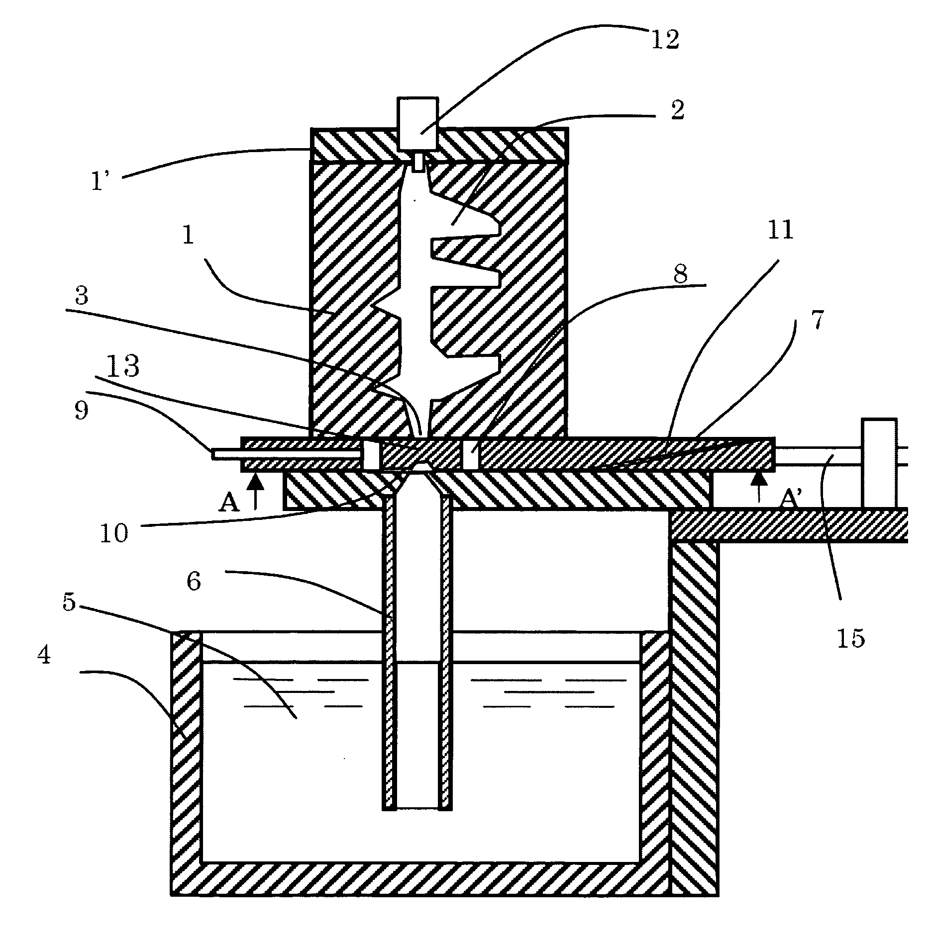
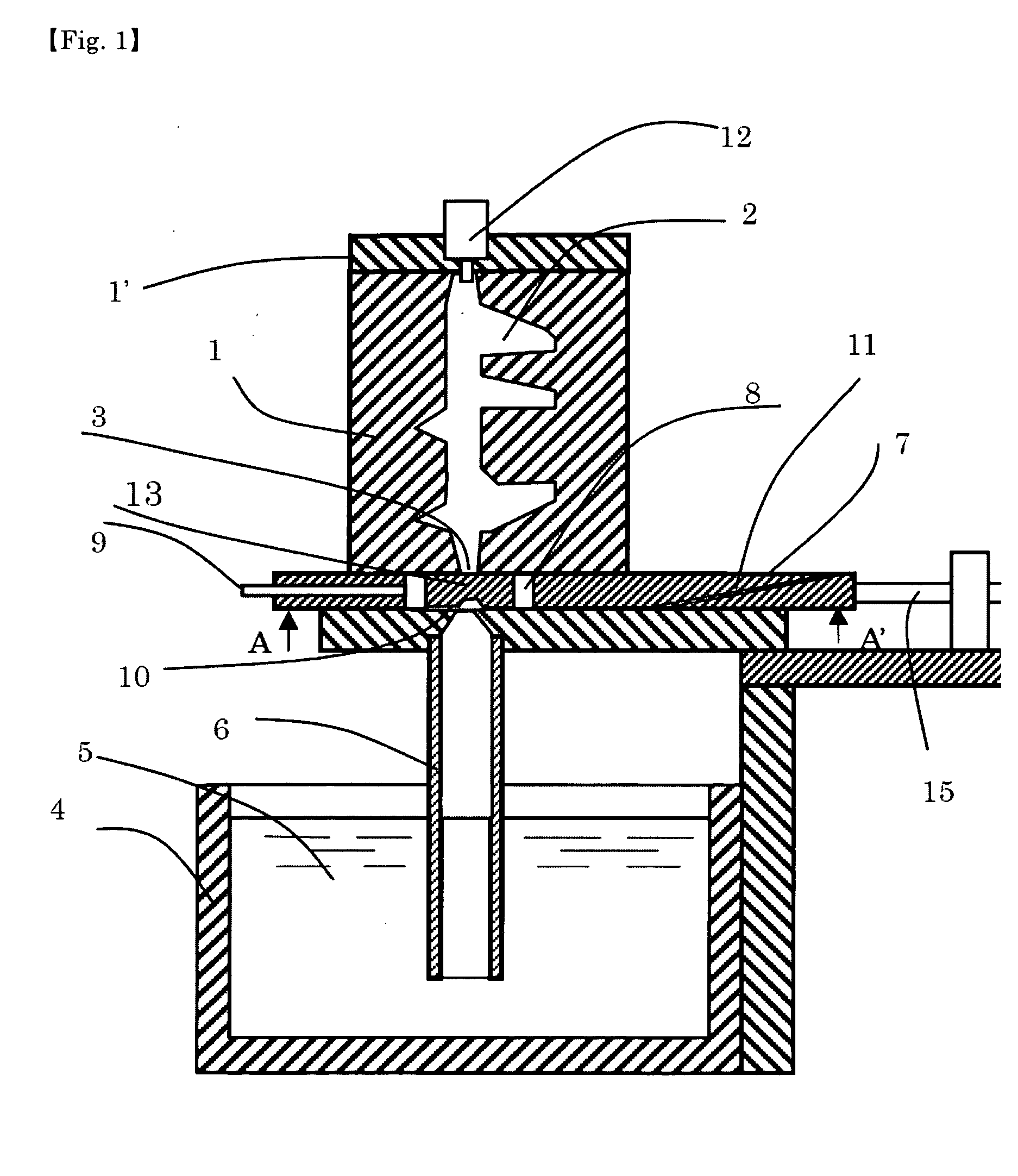
[0074]Example 1 is shown in FIG. 1. In the present embodiment, the space between a gate 3 of the lower portion of a die cavity 2 inside dies land 1′ which corresponds to a shape of a product, and a feeding tube 6 in which a molten metal 5 is immersed in a holding furnace or melting furnace 4, is closed with a sealing plate 7 (shown from below in FIG. 2), and an opening 8 provided in the die cavity 2 and the sealing plate 7 is depressurized. In this state, the opening 8 is depressurized as a result of only being connected to the die cavity 2 through a thin plate-like groove. Although this groove is preferably formed in the sealing plate, it may also be provided in the lower portion of the die. Next, molten metal is sucked by depressurizing the inside of the feeding tube 6 through a feeding tube depressurizing pipe 9 and a pressure reduction vent 10 provided in the sealing plate in the upper portion of the feeding tube 6, causing the molten metal to rise while maintaining the surface ...

example 2

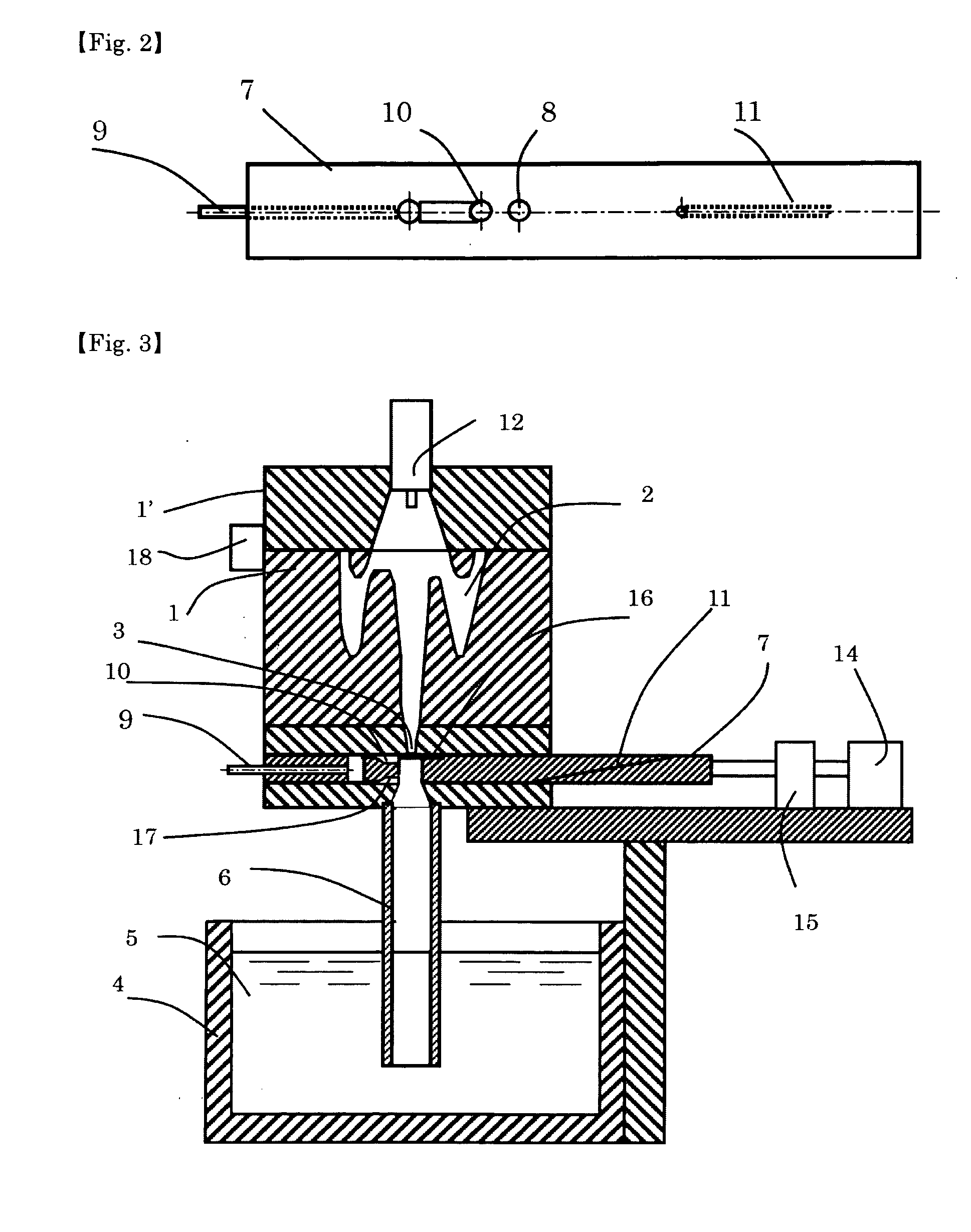
[0081]In FIG. 3, a pure Al plate having a thickness of about 100 μm is used as a consumable seal 16 for the seal of the gate 3. The structure of the sealing plate in this case is shown in FIG. 4. The consumable seal 16 is installed by moving the sealing plate 7 to the left, placing the consumable seal 16 at a holding section, and moving to the upper portion of the feeding tube 6. When the die cavity 2 is depressurized, the consumable seal 16 is adhered to the gate 3 by the attractive force thereof thereby sealing the gate 3. Alternatively, a consumable seal may be affixed to the gate 3 at another location while depressurizing the die cavity.

[0082]Subsequently, the inside of the feeding tube is depressurized from the feeding tube depressurizing pipe 9 through pressure reduction vents 10 and 17 in the upper end of the feeding tube 6. When the surface of the molten metal reaches the pressure reduction vent 17, oxide films and molten metal having the possibility of containing suspended ...

example 3

[0083]FIG. 5 shows Example 3 in which a portion 19 of the feeding tube 6 is made of graphite or silicon nitride having high thermal conductivity, the portion of the feeding tube 6 is cooled by air cooling or by employing a cold crucible-like structure (water-cooled copper cylinder provided with slits), a solid phase is made to precipitate in the molten metal simultaneous to stirring the molten metal using the action of electromagnetic force and then supplying the molten metal to the die cavity in the same manner as Example 1 or 2 with the precipitated solid phase in a granulated state. In addition to using the principle of an electric motor, electromagnetic force may be applied by other methods such as rotating a permanent magnet or using the principle of a linear motor. A combination of these methods may also be used. In addition, the electromagnetic stirring described above may also be carried out in a horizontal portion by having the feeding tube protrude outside the holding furn...


PUM

PropertyMeasurementUnit
depthaaaaaaaaaa
atmospheric pressureaaaaaaaaaa
thicknessaaaaaaaaaa

Abstract

A casting method and apparatus are provided capable of producing high-quality castings having extremely few defects attributable to entrainment of gas, oxide film and the like both economically and while conserving energy. Namely, a sealing plate having a seal, an opening and a pressure reduction vent is arranged between a gate of a die cavity and a feeding tube, and the die cavity is depressurized by sealing the gate. Next, the inside of the feeding tube is depressurized through the pressure reduction vent provided in the lower surface of the sealing plate to suck a molten metal, the opening of the sealing plate is moved to between the gate and the feeding tube when the molten metal has entered the pressure reduction vent, and the molten metal is filled into the die cavity due to the pressure difference between the die cavity and the molten metal in the feeding tube. A consumable seal made of a material similar to the molten metal can also be used for the gate seal. Once the molten metal has filled the die cavity, the sealing plate is immediately moved to close the gate, and the molten metal is made to drop down into a holding furnace by allowing external gas pressure to act on the surface of the molten metal in the feeding tube through an external gas ventilation port. Moreover, unsolidified molten metal in the die cavity may be pressurized as necessary.

Description

[0001]This application is a continuation application of International Application PCT / JP2007 / 073637 filed Nov. 30, 2007, which in turn claims priority from Japanese Patent Application No. JP2007-098865 filed on Mar. 6, 2007. Both applications are incorporated herein by reference.TECHNICAL FIELD[0002]The present invention relates to a material processing method using solidification.BACKGROUND ART[0003]In casting processing or resin injection molding and the like using solidification of a melted material, air or other gas is entrained when filling the die cavity with molten metal resulting in gas defects, while the entrained minute amounts of gas and the like also contribute to the occurrence of shrinkage cavity defects. In particular, since oxide films easily form on the surface of the molten metal in the case of Al alloys or Mg alloys and the like, these films are easily entrained during the mold filling and causes inferior mechanical and chemical properties of the cast product, the...

Claims


Application Information

Patent Timeline
Patent Type & Authority Applications(United States)
IPC IPC(8): B22D27/02B22D18/06B22C19/00
CPCB22D18/04B22D18/08B22D18/06
Inventor OHNAKA, ITSUO
Owner IE SOLUTION CORP
Learn More