Sheet material information detection apparatus, sheet material processing apparatus, and sheet material information detection method

a technology of material information and detection apparatus, applied in electrographic processes, instruments, devices using optical means, etc., can solve the problems of limited range of sheet materials which can be detected with high accuracy, inability to identify thin sheets of material with high accuracy, and difficulty in setting optimum processing conditions. , to achieve the effect of high accuracy

Inactive Publication Date: 2009-09-24
CANON KK
View PDF21 Cites 0 Cited by
  • Summary
  • Abstract
  • Description
  • Claims
  • Application Information

AI Technical Summary

Benefits of technology

[0014]The present invention provides a sheet material information detection apparatus, which can cope with high-speed transportation of ...

Problems solved by technology

On the other hand, with the diversification of sheet materials and the diversification of processing contents, the number of items to be set by a user becomes enormous, thereby making it difficult to set the optimum processing conditions.
However, when a combination of a motion member, an acceleration mechanism of the motion member, and an impact reception member (support member) is determined, the range of sheet materials which can be detected with high accuracy will be limited.
However, when the motion member is made heavier or the collision velocity is made higher, a large impact force ignoring a deflection resistance of the thin sheet material is detected, so that the thin sheet material cannot be identified with high accuracy.
Further, there is a fear that a trace of collision may be left on the sheet material.
With the system as disclosed in Japanese Patent Application Laid-Open No. 2004-38983, an arithmetic operation is performed ...

Method used


Image

  • Sheet material information detection apparatus, sheet material processing apparatus, and sheet material information detection method
  • Sheet material information detection apparatus, sheet material processing apparatus, and sheet material information detection method
  • Sheet material information detection apparatus, sheet material processing apparatus, and sheet material information detection method

Examples


first embodiment

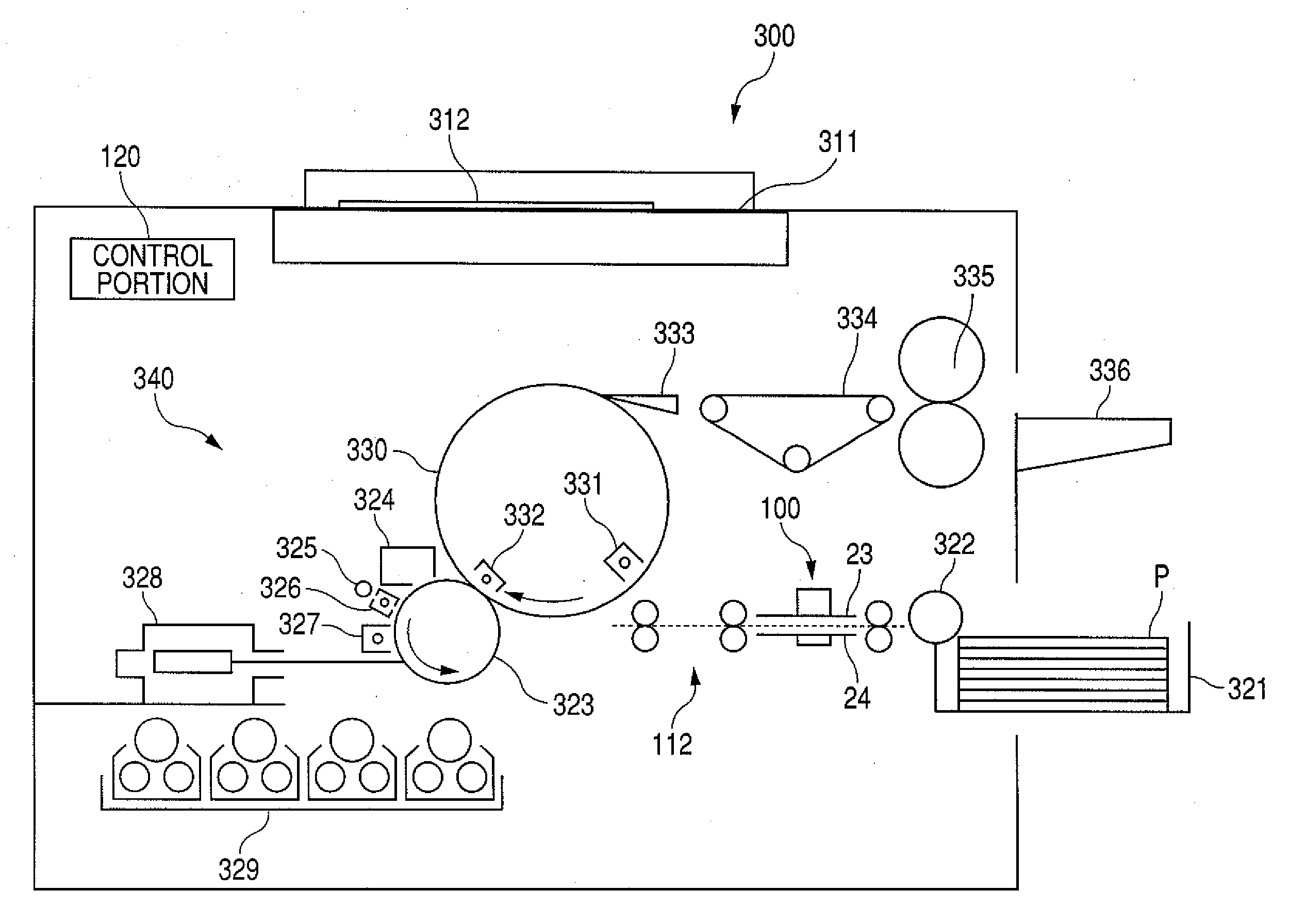
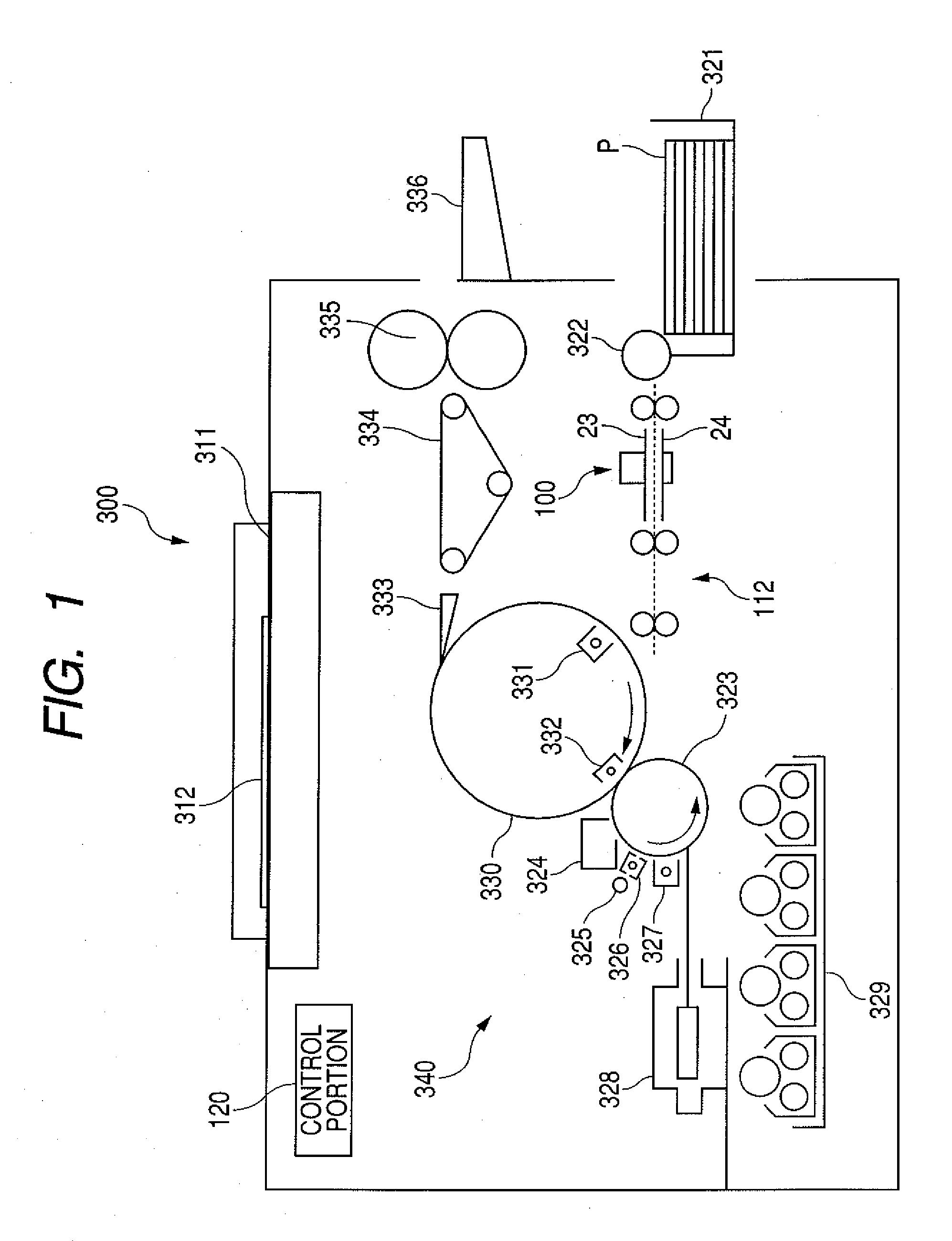
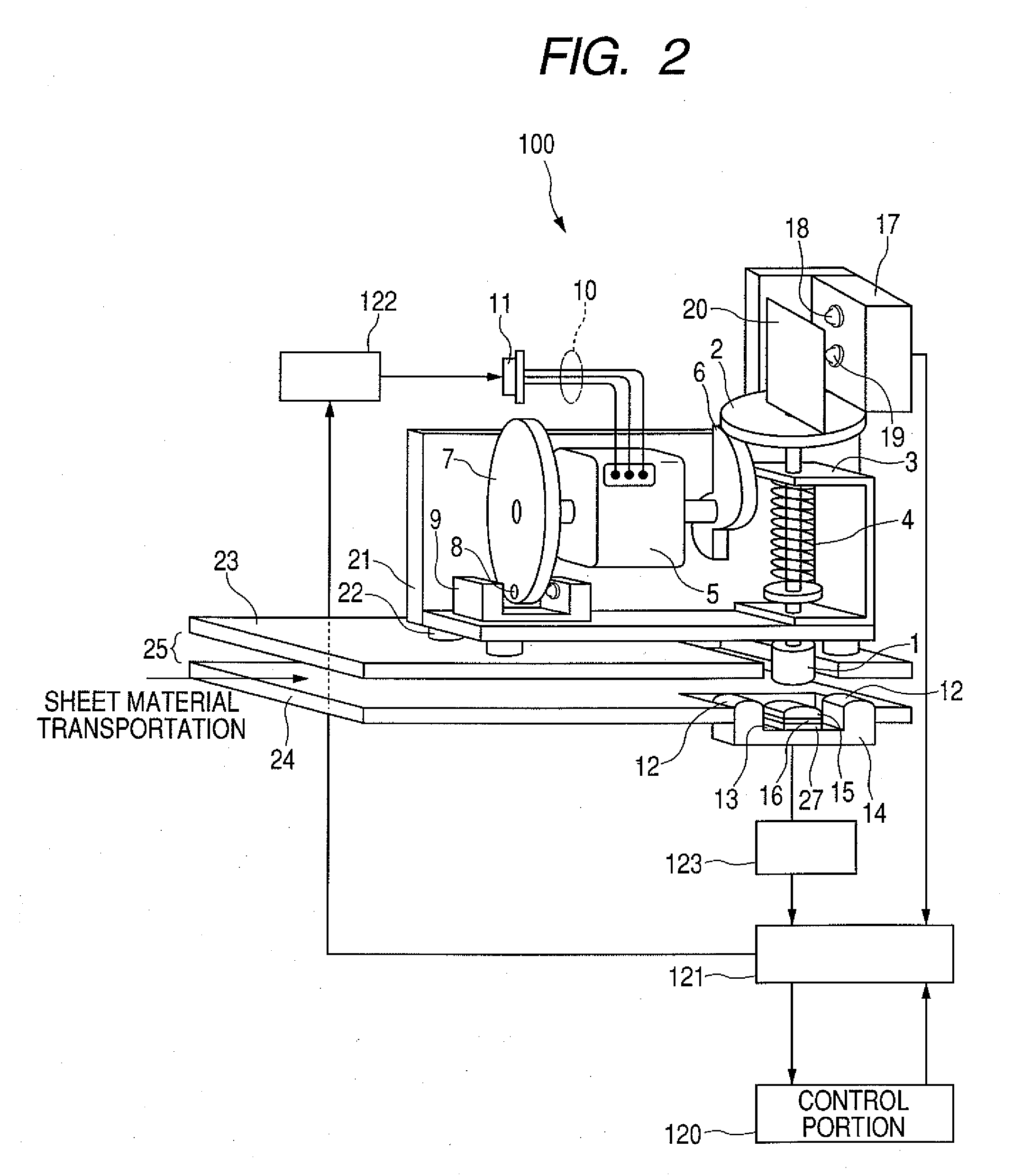
[0034]FIG. 1 is an explanatory diagram of a structure of an image forming apparatus. FIG. 2 is an explanatory view of a structure of a sheet material information detection apparatus according to a first embodiment of the present invention. FIGS. 3A to 3D are explanatory diagrams illustrating a collision process of a motion member. FIG. 4 is a graphical representation of a result of detection by a motion detection portion. FIG. 5 is a flow chart illustrating an operation of the sheet material information detection apparatus.

[0035]As illustrated in FIG. 1, an image forming apparatus 300 is a color copying machine for performing image formation on a sheet material P by an image formation process portion 340. A reading unit 311 reads mage information of a color original 312. The read information is converted into color signals corresponding to four colors of toner, which are cyan, magenta, yellow, and block.

[0036]On the other hand, the sheet material P accommodated in a cassette 321 is ...

second embodiment

[0099]FIG. 6 is a flow chart of control of the sheet material processing apparatus according to a second embodiment of the present invention. FIG. 7 is a table of sheet material information outputs using a measuring portion and a piezoelectric element. In the second embodiment of the present invention, description will be made of control in a case where the sheet material information detection apparatus 100 described with reference to FIGS. 2 to 4 is mounted on a sheet material processing apparatus other than the image forming apparatus 300.

[0100]First, the sheet material processing apparatus starts a sheet material processing operation to start transporting a sheet material (S21). Starting of the sheet material processing operation is performed by a user (operator) of the sheet material processing apparatus pressing a start button on an apparatus main body, by sending a processing command from a peripheral equipment such as an external computer or a camera connected thereto, or the...

third embodiment

[0117]FIG. 8 is an explanatory view of a structure of a sheet material information detection apparatus according to a third embodiment of the present invention. A sheet material information detection apparatus 200 according to the third embodiment of the present invention includes, as main components thereof, a motion member 31 for collision with the sheet material, an acceleration unit for imparting a predetermined velocity to the motion member 31, a support member for supporting the sheet material, and a measuring unit for measuring a motion of the motion member 31. In the third embodiment of the present invention, the motion member 31 is allowed to collide with the sheet material through a rotational motion in which the motion member 31 is allowed to swing about a bearing 33. Further, for a measuring portion 47, a transmission optical sensor which is lower in cost than a laser Doppler velocimeter used in the first embodiment of the present invention is adopted. The measuring port...


PUM


Abstract

A motion member (1) urged by an application spring 4 is made to collide with a surface of a sheet material supported by a support member (14) so as to be deflectable and deformable. The velocity of the motion member (1) during the collision process is detected every second by a measuring portion (17) of a laser Doppler velocimeter. A control circuit (121) measures the velocity of the motion member (1) immediately before the collision of the motion member (1) with the sheet material, the time period of deflection deformation until the sheet material collides with an opposing member (15), and the time period of compression deformation after the collision of the sheet material with the opposing member (15), and outputs a result thereof as sheet material information to a control portion (120). The timing at which the sheet material collides with the opposing member (15) is detected by an output of a piezoelectric element (16) connected to the opposing member (15).

Description

TECHNICAL FIELD[0001]The present invention relates to a sheet material information detection apparatus which allows a motion member to collide with a sheet material to generate an output by which the sheet material can be identified, and more particularly, to a mechanism for detecting an impact force through a sheet material. Further, the present invention relates to a sheet material processing apparatus and a sheet material information detection method.BACKGROUND ART[0002]In recent years, in a technical field of sheet material processing apparatuses, typified by image forming apparatuses (such as LBPs, copying machines, and inkjet printers), the diversification of types of sheet materials to be processed has proceeded, and the diversification of users and use environment of the sheet material processing apparatus has also proceeded. As far as the image forming apparatus is concerned, for the thus diversified sheet materials, there is an increasing need for improvement of quality (h...

Claims


Application Information

Patent Timeline
IPC IPC(8): G03G15/00G01N3/30G01B11/14G01P3/36
CPCG03G2215/00746G03G15/5029G03G15/5025G03G2215/00738G03G2215/00742
Inventor KAWASAKI, TAKEHIKOKANEKO, NORIO
Owner CANON KK
Why Eureka
Try Eureka