
Machine tool with chip processing function

a technology of processing function and machine tool, which is applied in the direction of manufacturing tools, cutting cutters, cutting inserts, etc., can solve the problems of reducing tool life, increasing the quantity of cutting heat, and reducing the cutting resistance, so as to improve the general machinability of the machine, reduce the amount of cutting heat, and reduce the effect of cutting resistan

Inactive Publication Date: 2009-09-03
NAGOYA UNIVERSITY +1
View PDF34 Cites 9 Cited by
  • Summary
  • Abstract
  • Description
  • Claims
  • Application Information

AI Technical Summary

Benefits of technology

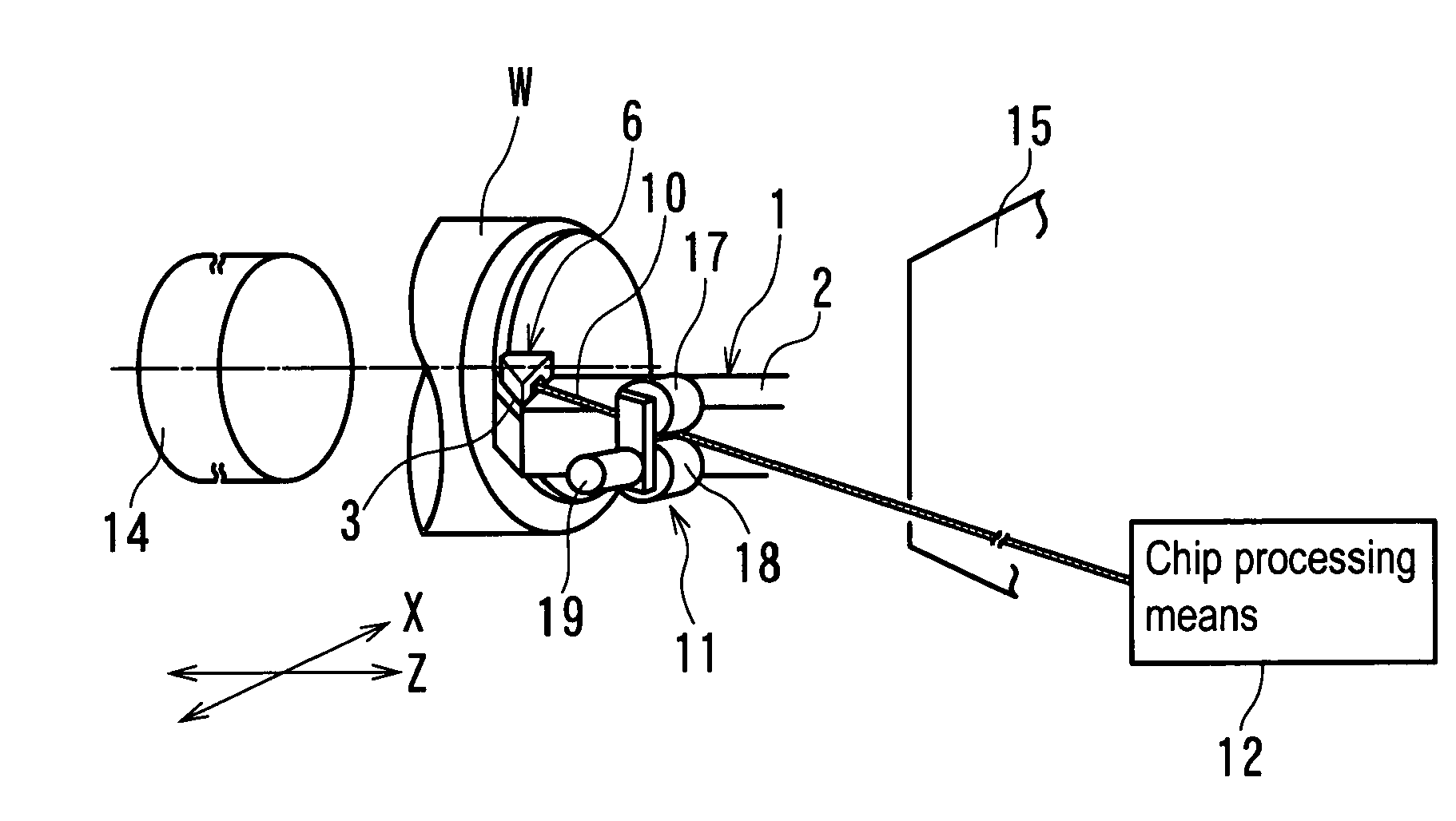
[0021]In this configuration, the chip guiding means is provided to guide the chip to the tensile force applying means, thus allowing processing to be performed with the chip under tension. Thus, consecutive chip processing can be carried out even on ductile materials such as press steel, heat resistant alloys, and soft aluminum on which the chip breaker fails to act. Since chip controllability is improved, automation for the ductile materials is facilitated, thus improving yield and machining accuracy. Furthermore, a technique of performing cutting with the chip under tension can be implemented. The cutting resistance, required power, resulting heat, and the like which are associated with friction can be reduced to improve the machinability in general. At the same time, the cutting efficiency can be improved, and the tool life can be prolonged. The prolonged tool life resulting from the reduced cutting resistance means, in the opposite sense, that with the tool life remaining unchanged, faster or heavier cutting can be achieved. The present embodiment thus increases efficiency compared to the conventional art. Furthermore, where a cutting-direction component (radial force) of a cutting force is offset by the tensile force, the amount of cut is prevented from varying depending on the cutting force. This significantly contributes to improving the machining accuracy.
[0056]When the machine tool includes the chip processing means for severing or winding the chip having passed through the tensile force applying means, the processing of the chip is facilitated. Furthermore, the range of available options for the chip processing means can be increased.

Problems solved by technology

In particular, poor chip controllability is the worst factor hindering automation because of entangled chips and the like.
When a cutting speed is increased to allow the cutting operation to be efficiently achieved, the quantity of cutting heat increases to reduce the tool life.
However, the use of the cutting oil may disadvantageously affect environments.
Thus, the chip breaker often fails to act on ductile materials such as steel used for press working and heat resistant alloys.
This may result in the entangled chip or the damaged finished surface.
Furthermore, even where the chip breaker functions properly, the cutting resistance varies periodically, possibly posing a vibration problem or reducing the machining accuracy.
Thus, if the hollow guide path or guide groove has a narrow inlet, the chip is likely to be caught at the inlet.
Thus, the chip is jammed in the hollow guide path or guide groove.
Consequently, putting the hollow guide path or guide groove to practical use is difficult.
The technique cannot be applied to general turning operations.
Thus, this technique fails to act on the general turning operations, in which the original flow direction, width, and occurrence position of the chip vary depending on the machining conditions.
However, since no practical method for pulling the chip is available, the technique has not been put to practical use for a long time.
Without the regulation, the roller fails to catch the tip portion of the chip and thus cannot be put to practical use.
Since the chip may be curled and the flow direction may vary depending on the cutting conditions or the like, regulating the flow path is difficult.

Method used


Image

  • Machine tool with chip processing function
  • Machine tool with chip processing function
  • Machine tool with chip processing function

Examples


Embodiment Construction

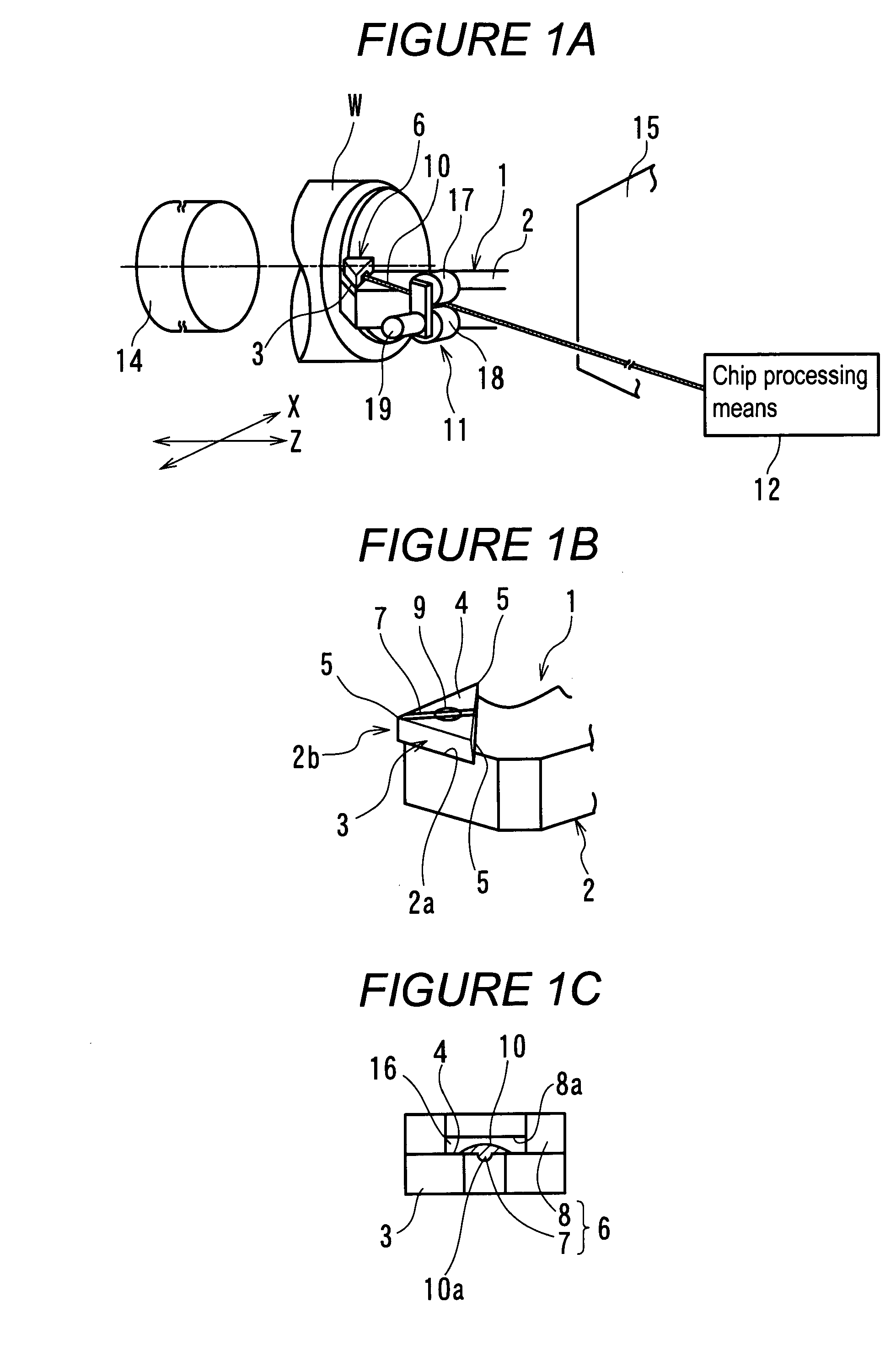
[0087]A first embodiment of the present invention will be described with reference to FIGS. 1 to 22. FIG. 1 schematically shows a machine tool with a chip processing function. The machine tool brings a cutting tool 1 into abutting contact with a rotating workpiece W for cutting. The machine tool includes a tensile force applying means 11 for applying a tensile force to a chip 10 continuing with a workpiece W and flowing from a cutting edge line 5 of the cutting tool 1, a chip guiding means 6 for guising the chip 10 to the tensile force applying means 11, and a chip processing means 12 for processing the chip 10 having passed through the tensile force applying means 11. Furthermore, a guide path (not shown in the drawings) such as a pipe is provided between the tensile force applying means 11 and the chip processing means 12 so that the chip 10 is passed and guided through the guide path. The chip processing means 12 is a device that carries out a process of severing or winding the c...


PUM

PropertyMeasurementUnit
tip angleaaaaaaaaaa
nose radiusaaaaaaaaaa
cutting speedaaaaaaaaaa

Abstract

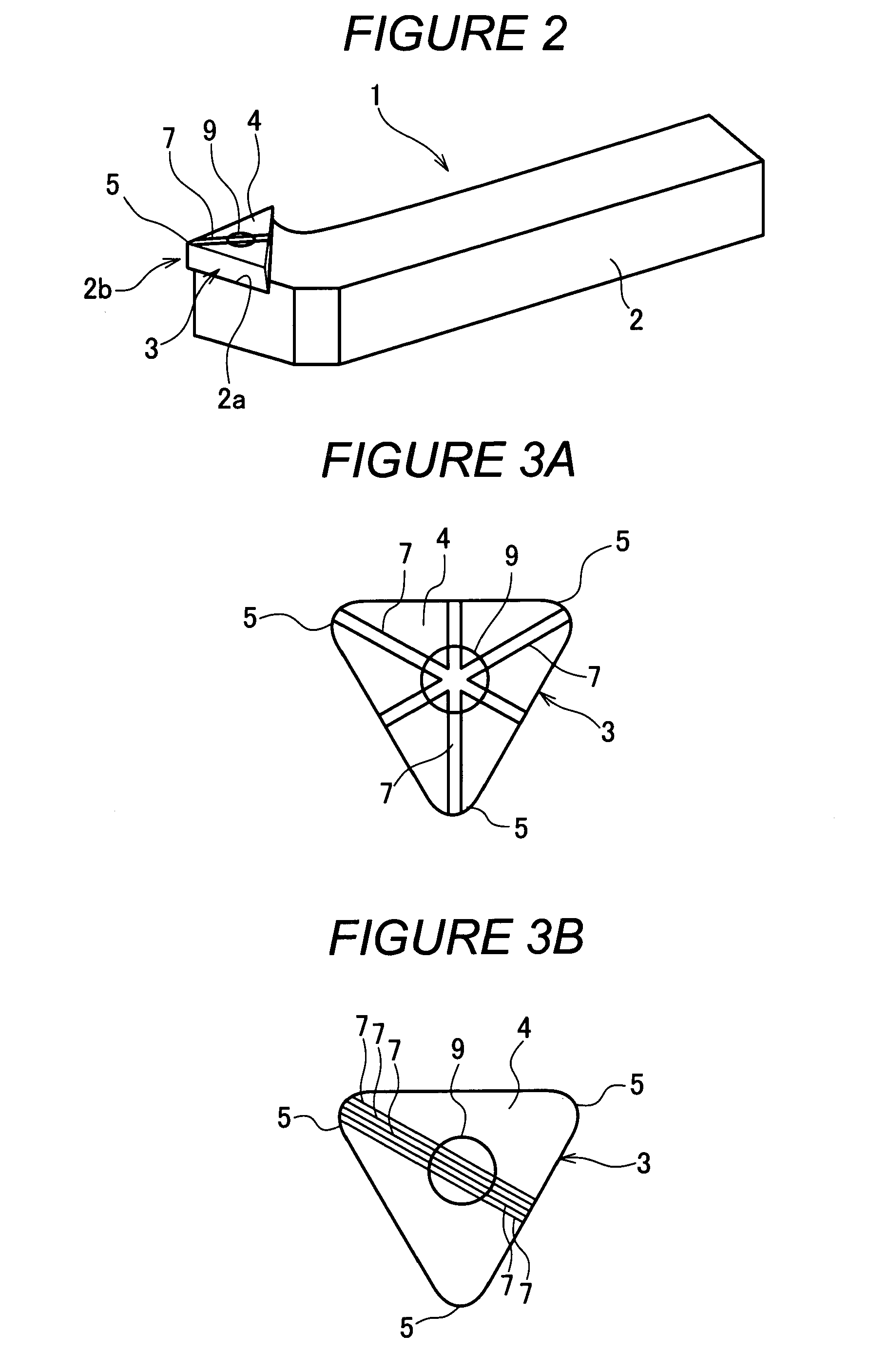
The present invention provides a machine tool which allows a chip to be guided in a desired direction and which enables consecutive chip processing, the machine tool further enabling a reduction in cutting resistance, required power, resulting heat, friction of a tool, and the like. The machine tool includes a chip processing means 12 for continuously processing a chip 10 flowing from a workpiece W, a tensile force applying means 11 for applying a tensile force to the chip 10 at a position closer to a cutting edge line 5 than the means 12, and a chip guiding means 6 for guiding the chip 10 to the means 11. As the chip guiding means 6, a guide groove 7 is formed in a rake face of a cutting tool. The guide groove 7 has a smaller width than the chip 10. A part of a rake surface side of the chip 10 is fitted into the guide groove 7 to allow the chip 10 to be guided.

Description

FIELD OF THE INVENTION[0001]The present invention relates to a machine tool with a chip guiding function which is used for turning operation or the like, and in particular, to a machine tool with a chip processing function which is suitable for ductile materials.BACKGROUND OF THE INVENTION[0002]In recent years, with developed mass production and improved performance of industrial products, there has been a demand for increased efficiency and precision of cutting operation. To meet the demand, appropriate control of chips and an increase in cutting speed are required. In connection with the cutting operation, chip controllability, tool life, cutting resistance, and machining accuracy are called four machinability items. Efforts have been made to improve each of the items. In particular, poor chip controllability is the worst factor hindering automation because of entangled chips and the like.[0003]To improve the chip controllability, a chip breaker is generally used to heavily curl a...

Claims


Application Information

Patent Timeline
Patent Type & Authority Applications(United States)
IPC IPC(8): B26D3/00
CPCB23B27/16B23B27/22B23B29/04B23B29/12Y10T407/235B23B2200/087B23B2260/116B23B2270/30B23B2200/083
Inventor SHAMOTO, EIJIKOIDE, TOMIO
Owner NAGOYA UNIVERSITY
Learn More