
Batteries and electrodes for use thereof

Inactive Publication Date: 2009-08-13
MASSACHUSETTS INST OF TECH
View PDF99 Cites 83 Cited by
  • Summary
  • Abstract
  • Description
  • Claims
  • Application Information

AI Technical Summary

Benefits of technology

[0021]In another aspect, the present invention is directed to a method of making one or more of the embodiments described herein, for example, a small-scale battery or a or microbattery. In another aspect, the present invention is directed to a method of using one or more of the embodiments described herein, for example, a small-scale battery or a microbattery.
[0022]Other advantages and novel features of the present invention will become apparent from the following detailed descript

Problems solved by technology

However, the laminated construction techniques of current high energy density batteries (e.g., lithium ion batteries), now approaching their engineering limits, have inefficient mass and volume utilization, with only 30% to 40% of the available device volume being used for ion storage.
Attempts to increase power density, for instance by using thinner electrodes, typically has come at the expense of energy density.

Method used


Image

  • Batteries and electrodes for use thereof
  • Batteries and electrodes for use thereof
  • Batteries and electrodes for use thereof

Examples


example 1

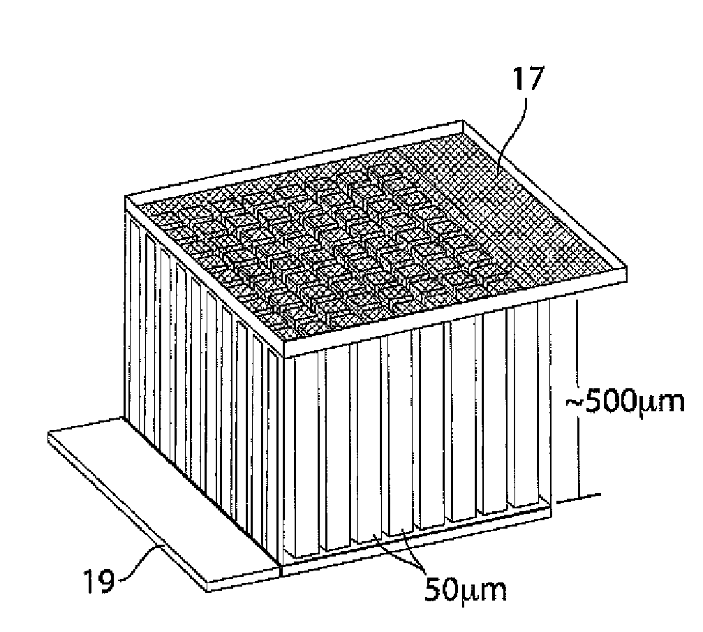
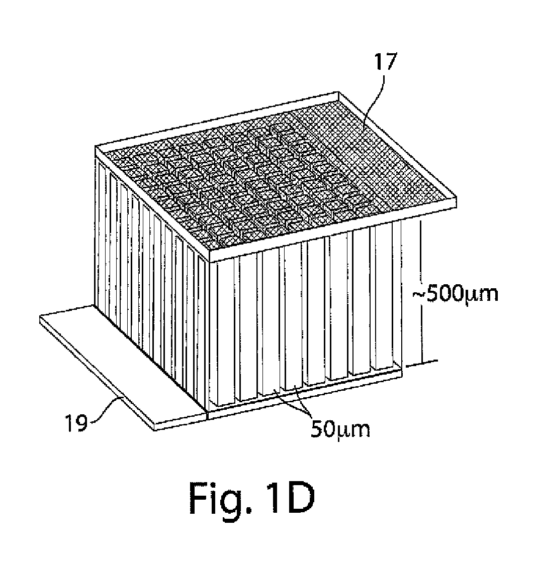
[0109]This example illustrates an integrally packaged, solid-state lithium rechargeable microbattery with a 3-dimensional interpenetrating-electrode internal architecture, in accordance with one embodiment of the invention. Such microbatteries may have the capability for outer package aspect ratios of (for example) less than 5:1 for maximum to minimum dimensions (i.e., not restricted to thin planar configurations), active materials packaging fraction of >75% in a 1 mm3 volume, under which conditions they will exceed an initial energy density target of 200 W h / l by a factor of 3 to 7. The approach in this example will use currently available and proven cathode and anode materials, but does not exclude higher energy or higher rate active materials in the future.

[0110]The microbatteries in this example will allow energy densities of about 200 W h / l to about 1500 W h / L to be achieved, depending on the electrochemical couple used, and specific design parameters, as discussed below. Micro...

example 2

[0119]In this example, 3D batteries having periodic or aperiodic interpenetrating electrodes are used since their electronic conductivity is typically higher than ionic conductivity in battery materials. Interpenetrating electrodes of high aspect ratio can have shorter ion diffusion length between electrodes while still taking advantage of the higher electronic conductivity along the electrodes to extract current. In the solid-state diffusion limit, the dimension that may determine the utilization of the battery capacity is the half-width x of the electrode features, for which the discharge time is t=x2 / DLi.

[0120]Using tabulated room-temperature lithium chemical diffusivities (DLi) for spinel and layered structure intercalation oxides, which fall in the range 1×10⁻⁹ cm2 / sec to 5×10⁻⁹ cm2 / sec, for a maximum 2C discharge rate (t=1800 sec), a half-thicknesses of about 6 to about 30 micrometers is useful. These kinetics and their limitations on particle dimensions are well-known to the ...

example 3

[0130]In this example, it is shown that a porous sintered electrode of LiCoO2 of greater than 0.5 mm minimum cross-sectional dimension that is infused with a liquid electrolyte can, surprisingly and unexpectedly, be electrochemically cycled while obtaining nearly all of the available ion storage capacity over at least 20 cycles at C / 20 rate with minimal capacity fade and no apparent detrimental mechanical damage to the electrode. This shows that such electrodes can effectively be used in certain batteries of the invention.

[0131]A battery grade LiCoO2 powder from Seimi Corporation (Japan) having 10.7 micrometers d50 particle size was pressed and fired at 1100° C. in air to form a porous sintered ceramic having about 85% of the theoretical density of LiCoO2. In one instance, a plate of this electrode having 0.66 mm thickness was prepared, as shown in FIGS. 8A and 8B. This electrode plate was attached to a gold foil current collector and assembled for testing in a sealed polymer pouch-...


PUM


Abstract

The present invention generally relates to batteries or other electrochemical devices, and systems and materials for use in these, including novel electrode materials and designs. In some embodiments, the present invention relates to small-scale batteries or microbatteries. For example, in one aspect of the invention, a battery may have a volume of no more than about 5 mm3, while having an energy density of at least about 400 W h / l. In some cases, the battery may include a electrode comprising a porous electroactive compound. In some embodiments, the pores of the porous electrode may be at least partially filled with a liquid such as a liquid electrolyte. The electrode may be able to withstand repeated charging and discharging. In some cases, the electrode may have a plurality of protrusions and / or a wall (which may surround the protrusions, if present); however, in other cases, there may be no protrusions or walls. The electrode may be formed from a unitary material. In certain embodiments, a nonporous electrolyte may be disposed onto the electrode. Such an electrolyte may allow ionic transport (e.g., of lithium ions) while preventing dendritic formation due to the lack of pores. In certain embodiments the porous electrode has a surface that is denser than its interior. Other aspects of the invention are directed to techniques of making such electrodes or batteries, techniques of forming electrical connections to and packaging such batteries, techniques of using such electrodes or batteries, or the like.

Description

RELATED APPLICATIONS[0001]This application is a continuation-in-part of U.S. patent application Ser. No. 12 / 126,841, filed May 23, 2008, entitled “Batteries and Electrodes For Use Thereof,” by Chiang, et al., which application claims the benefit of U.S. Provisional Patent Application Ser. No. 60 / 931,819, filed May 25, 2007, by Chiang, et al., each incorporated herein by reference.GOVERNMENT FUNDING[0002]Research leading to various aspects of the present invention were sponsored, at least in part, by the U.S. Department of Defense, Grant No. NMA501-03-1-2004. The U.S. Government has certain rights in this invention.FIELD OF INVENTION[0003]The present invention generally relates to batteries or other electrochemical devices, and systems and materials for use in these, including novel electrode materials and designs. In some embodiments, the present invention relates to small-scale batteries or microbatteries.BACKGROUND[0004]Since the time of Volta, batteries and other electrochemical ...

Claims


Application Information

Patent Timeline
IPC IPC(8): H01M6/04H01M4/02H01M4/58H01M4/48H01M4/88H01M10/36
CPCH01M4/0426Y02E60/122H01M4/131H01M4/1391H01M4/1393H01M4/1397H01M4/485H01M4/505H01M4/525H01M4/661H01M4/664H01M4/667H01M10/0436H01M10/0472H01M10/052H01M10/0525H01M10/0562H01M10/0565H01M2004/021H01M4/0471Y02E60/10Y02P70/50
Inventor CHIANG, YET-MINGWARTENA, RYAN C.CHIN, TIMOTHY E.ERDONMEZ, CAN K.LAI, WEI
Owner MASSACHUSETTS INST OF TECH
Learn More