
Multi-user multi-gpu render server apparatus and methods

a multi-user, server technology, applied in the field of digital data processing, can solve the problems of long wait times for users during transfer, high computational intensity of rendering such images, and long wait times for users, and achieve the effect of smooth interaction and fast rendering times

Active Publication Date: 2009-08-13
PME IP
View PDF9 Cites 41 Cited by
  • Summary
  • Abstract
  • Description
  • Claims
  • Application Information

AI Technical Summary

Benefits of technology

[0017]A further aspect of the invention provides a graphics system, for example, of the type described above, in which the render server breaks down selected ones of the render requests into multiple smaller requests, i.e., requests which require less compute time and / or less graphics resources. A related aspect of the invention provides for scheduling the smaller (and other) requests so as to minimize an average time that a client computer waits for a response to a request. This allows (by way of non-limiting example) for concurrent treatment of requests and for serving multiple client computers with a single GPU without compromising interactivity.
[0020]A related aspect of the invention provides a system, for example, as described above wherein the render server combines render requests for simultaneous processing in such a way, that their total graphics resource requirements can be satisfied by resources (e.g., texture and frame buffer memory) on-board a single graphics board. This allows (by way of example) time-slicing between the simultaneously processed render requests without the computationally expensive swapping of graphics memory chunks in and out of main memory of the host (i.e., “host memory”).
[0021]Another aspect of the invention provides a graphics system, for example, of the type described above, that renders images at different resolution levels, e.g., rendering a low-resolution image from a low-resolution version of the input data while rotating the data set, thus enabling faster rendering times and thereby smoother interaction. A related aspect of the invention provides such a system that adapts the resolution to the network speed and or the available processing resources. Another related aspect of the invention provides such a system wherein the render server continuously monitors one or more of these parameters and thereby allows for continuous adaptation of the resolution.
[0022]Another aspect of the invention provides a graphics system, for example, of the type described above, wherein the render server keeps local resources (such as texture memory) on one of the graphics boards allocated for the processing of a particular set of related render requests. Related aspects of the invention provide (for example) for re-use of such allocated resources for the processing of a subsequent render request in the set, thus eliminating the need to re-upload the data from host memory to texture memory for such subsequent render requests. By way of example, the render server of such a system can keep the texture memory of a graphics board allocated to the rendition of interactive render requests for low resolution versions of a data set (e.g., user-driven requests for rotation of the data set), which need to be processed with a minimal latency to allow for smooth interaction but only require a small amount of texture memory.

Problems solved by technology

The rendition of such images can be quite compute intensive and therefore takes a long time on a standard computer, especially, when the data sets are large.
Second the data sets often need to be transferred from a central store (e.g., a main enterprise server), where they are normally stored, to those local workstations prior to analysis and visualization, thus potentially causing long wait times for the user during transfer.
However, most of these solutions do not allow applications to use graphics hardware acceleration.
However that pipeline could then not be used locally any longer and was also blocked for other users.
While such a solution is transparent to the application and therefore convenient for the application developers it is very limited, too.

Method used


Image

  • Multi-user multi-gpu render server apparatus and methods
  • Multi-user multi-gpu render server apparatus and methods
  • Multi-user multi-gpu render server apparatus and methods

Examples


Embodiment Construction

Overview

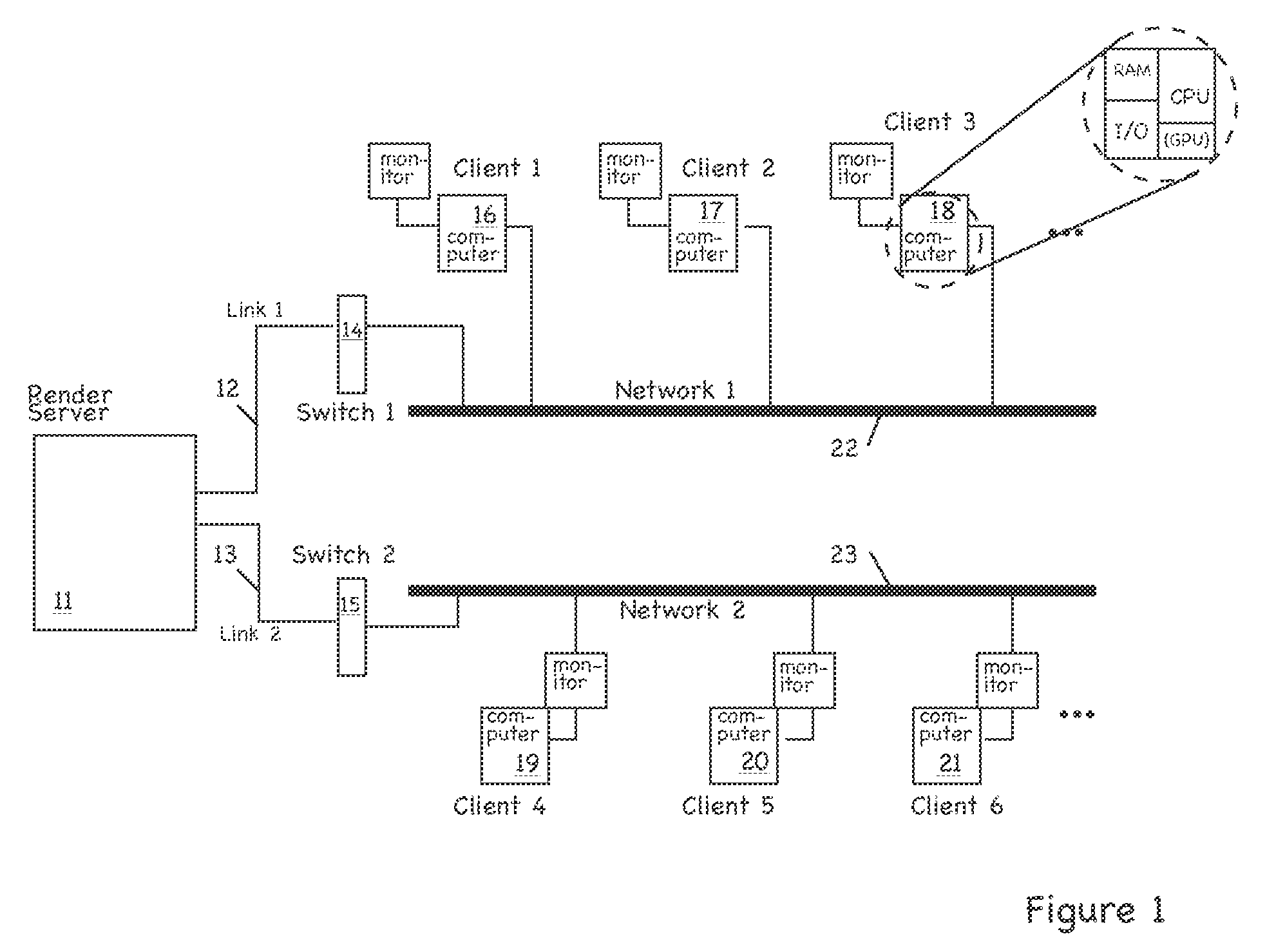
[0040]FIG. 1 depicts a system 10 according to one practice of the invention. A render server (or server digital data processor) 11, which is described in more detail below, is connected via one or more network interfaces 12, 13 and network devices such as switches or hubs 14, 15 to one or more networks 22, 23. The networks 22, 23 can be implemented utilizing Ethernet, WIFI, DSL and / or any other protocol technologies and they can be part of the Internet and / or form WANs (wide area networks), LANs (local area networks), or other types of networks known in the art.

[0041]One or more client computers (or “client digital data processors”) 16-21 are coupled to render server 11 for communications via the networks 22, 23. Client software running on each of the client computers 16-21 allows the respective computers 16-21 to establish a network connection to render server 11 on which server software is running. As the user interacts with the client software, messages are sent from the ...


PUM


Abstract

The invention provides, in some aspects, a system for rendering images, the system having one or more client digital data processors and a server digital data processor in communications coupling with the one or more client digital data processors, the server digital data processor having one or more graphics processing units. The system additionally comprises a render server module executing on the server digital data processor and in communications coupling with the graphics processing units, where the render server module issues a command in response to a request from a first client digital data processor. The graphics processing units on the server digital data processor simultaneously process image data in response to interleaved commands from (i) the render server module on behalf of the first client digital data processor, and (ii) one or more requests from (a) the render server module on behalf of any of the other client digital data processors, and (b) other functionality on the server digital data processor.

Description

[0001]This application claims the benefit of priority of U.S. Patent Application Ser. No. 60 / 989,881, filed Nov. 23, 2007, the teachings of which are incorporated herein by reference.BACKGROUND OF THE INVENTION[0002]The invention pertains to digital data processing and, more particularly, by way of example, to the visualization of image data. It has application to areas including medical imaging, atmospheric studies, astrophysics, and geophysics.[0003]3D and 4D image data is routinely acquired with computer tomographic scanners (CT), magnetic resonance imaging scanners (MRI), confocal microscopes, 3D ultrasound devices, positron emission tomographics (PET) and other imaging devices. The medical imaging market is just one example of a market that uses these devices. It is growing rapidly, with new CT scanners collecting ever greater amounts of data even more quickly than previous generation scanners. As this trend continues across many markets, the demand for better and faster visual...

Claims


Application Information

Patent Timeline
Patent Type & Authority Applications(United States)
IPC IPC(8): G06F13/14
CPCG06F3/14G06T15/005G06T2210/52H04L67/08G09G2360/06H04L12/58G09G5/363G06T1/20H04L51/216H04L51/10H04L51/00
Inventor WESTERHOFF, MALTESTALLING, DETLEV
Owner PME IP
Learn More