
Regular local clock buffer placement and latch clustering by iterative optimization

a local clock and latch technology, applied in the field of semiconductor chip fabrication and integrated circuits, can solve the problems of large number of cells, difficult to physically design without the aid of computers, and complex connections between cells, and achieve the effect of more flexibility in the placement of clock components

Inactive Publication Date: 2009-07-30
GLOBALFOUNDRIES INC
View PDF18 Cites 22 Cited by
  • Summary
  • Abstract
  • Description
  • Claims
  • Application Information

AI Technical Summary

Benefits of technology

[0013]It is therefore one object of the present invention to provide an improved placement method which provides more flexibility in the location of clock components.
[0014]It is another object of the present invention to provide such a method which improves clock power while reducing clock skew.
[0015]It is yet another object of the present invention to provide such a method which better utilizes local clock buffer latch drive strength.

Problems solved by technology

An IC may include a very large number of cells and require complicated connections between the cells.
Due to the large number of components and the details required by the fabrication process for very large scale integrated (VLSI) devices, physical design is not practical without the aid of computers.
While current placement techniques provide adequate placement of cells with regard to their data interconnections, there is an additional challenge for the designer in constructing a clock network for the cells and this challenge is becoming more difficult in the context of modem technologies such as those used to design low-power, 65-nanometer integrated circuits.
Low power circuits (e.g., around 20 watts or less for microprocessor chips) are becoming more prevalent due to power consumption problems.
In particular, power dissipation has become a limiting factor for the yield of high-performance circuit designs (operating at frequencies around 1 gigahertz or more) fabricated in deep submicron technologies.
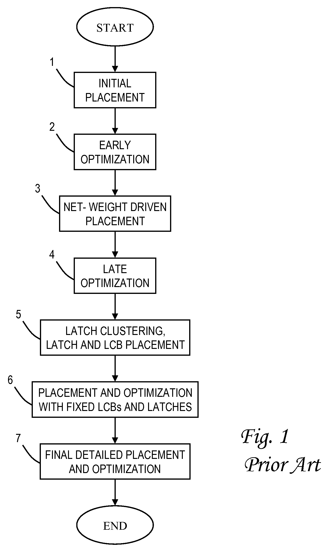
The resulting LCB-latch structure can be very large relative to other circuit elements involved in the placement process, and greatly impacts the timing of the circuit.
Unfortunately, the large macro synthesis flow may introduce additional constraints such as fixed clock pin locations which further limits the ability to optimize a design.

Method used


Image

  • Regular local clock buffer placement and latch clustering by iterative optimization
  • Regular local clock buffer placement and latch clustering by iterative optimization
  • Regular local clock buffer placement and latch clustering by iterative optimization

Examples


Embodiment Construction

)

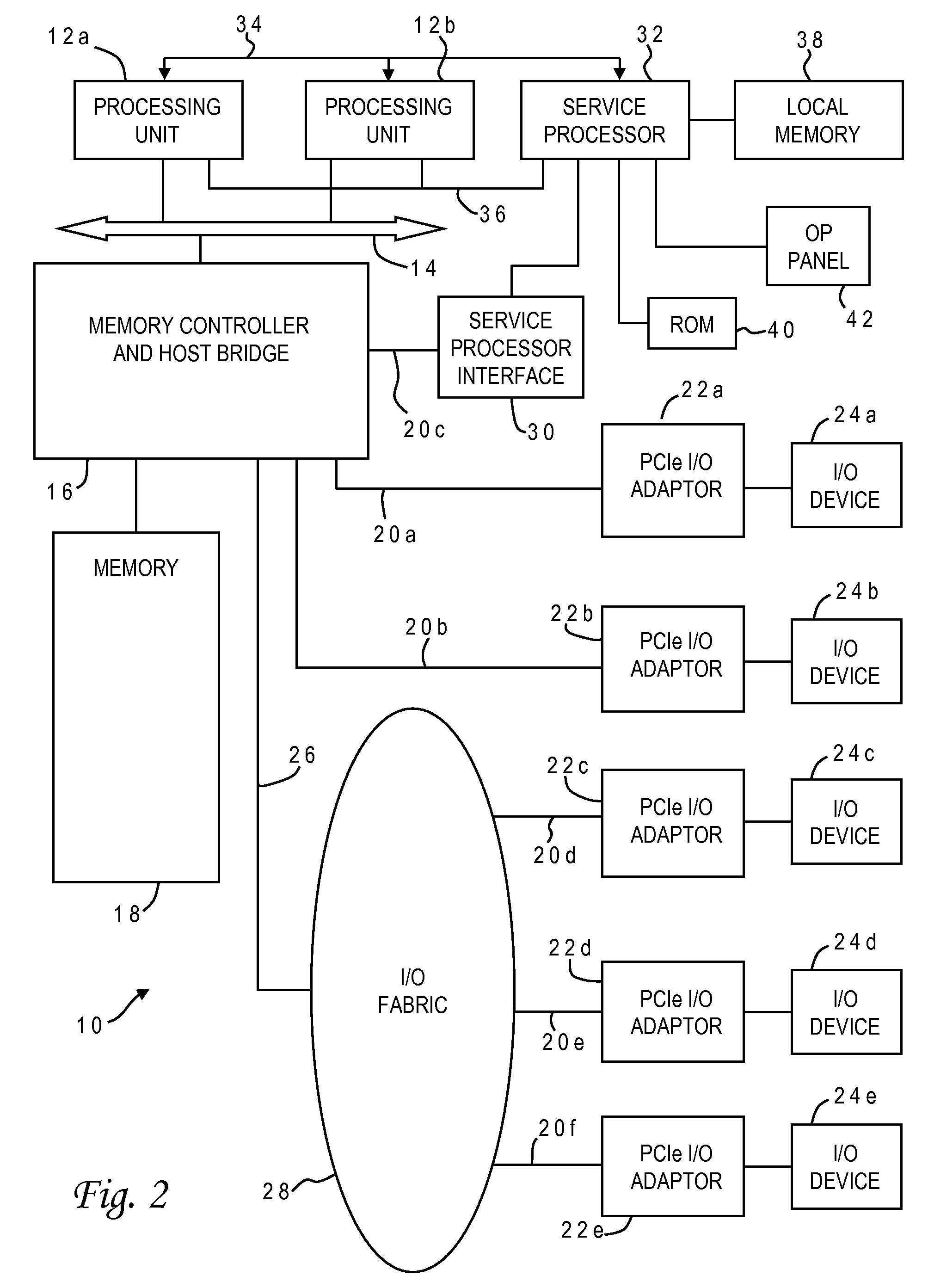
[0024]With reference now to the figures, and in particular with reference to FIG. 2, there is depicted one embodiment 10 of a computer system in which the present invention may be implemented. Computer system 10 is a symmetric multiprocessor (SMP) system having a plurality of processors 12a, 12b connected to a system bus 14. System bus 14 is further connected to a combined memory controller / host bridge (MC / HB) 16 which provides an interface to system memory 18. System memory 18 may be a local memory device or alternatively may include a plurality of distributed memory devices, preferably dynamic random-access memory (DRAM). There may be additional structures in the memory hierarchy which are not depicted, such as on-board (L1) and second-level (L2) or third-level (L3) caches.

[0025]MC / HB 16 also has an interface to peripheral component interconnect (PCI) Express links 20a, 20b, 20c. Each PCI Express (PCIe)link 20a, 20b is connected to a respective PCIe adaptor 22a, 22b, and each PCI...


PUM


Abstract

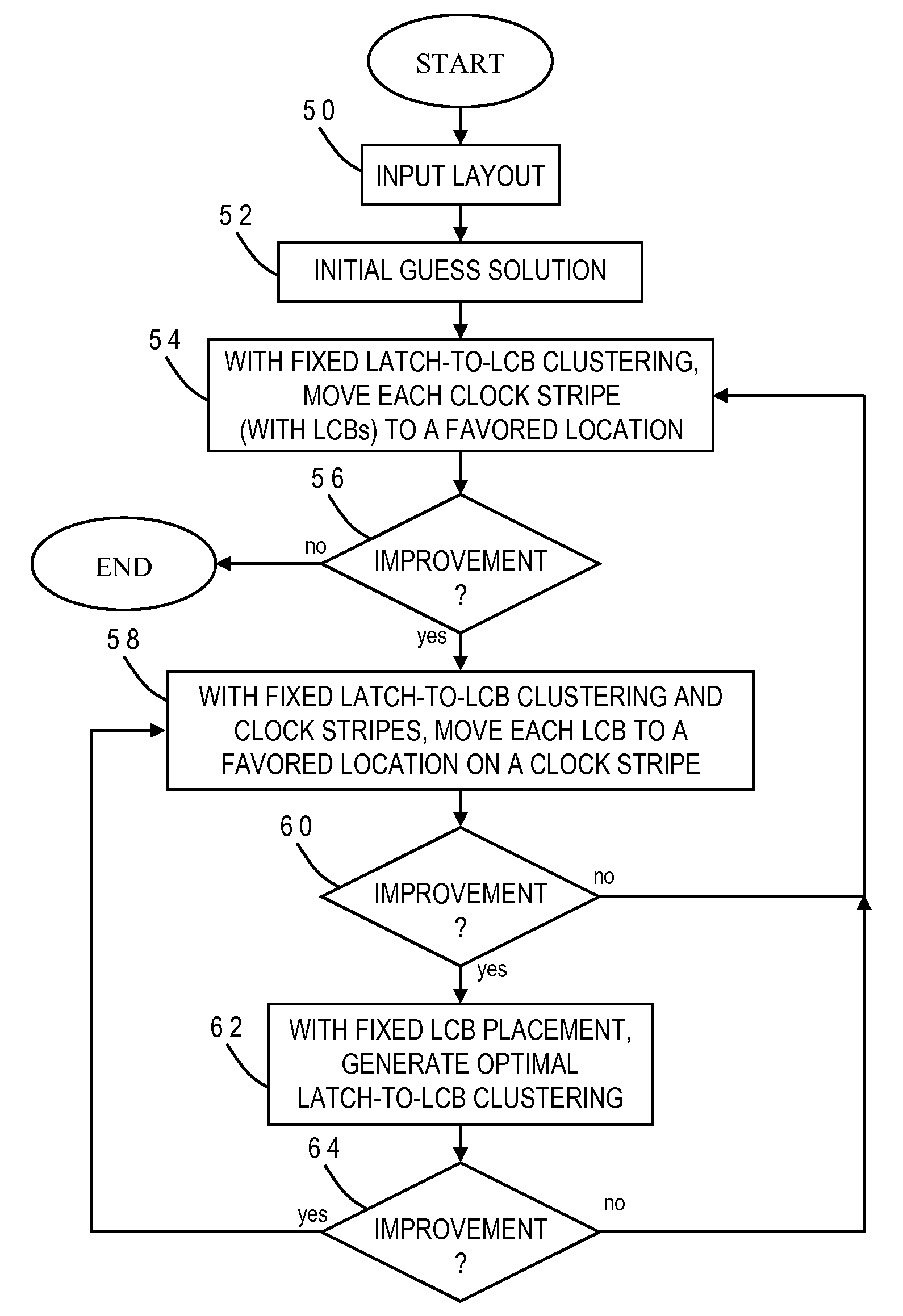
Power, routability and electromigration have become crucial issues in modem microprocessor designs. In high performance designs, clocks are the highest consumer of power. Arranging clocking components with regularity so as to minimize the capacitance of the clock nets can help reduce clock power, however, it may hurt performance due to some loss of flexibility in physically placing those components. The present invention provides techniques to optimally design a clock network by logically assigning clusters of the latches to respective clock distribution structures, placing clock pins at favored pin locations, and placing clock distribution structures directly underneath the clock pins. The clock distribution structures may be moved to favored distribution locations along the clock stripes, and new optimal clustering generated between the latches and the clock distribution structures. These three optimizations are preferably repeated iteratively to derive a local optimal solution for the clock network.

Description

STATEMENT REGARDING FEDERALLY SPONSORED RESEARCH OR DEVELOPMENT[0001]This invention was made with Government support under DARPA, HR0011-07-9-0002. THE GOVERNMENT HAS CERTAIN RIGHTS IN THIS INVENTION.BACKGROUND OF THE INVENTION[0002]1. Field of the Invention[0003]The present invention generally relates to the fabrication and design of semiconductor chips and integrated circuits, and more particularly to a method of designing the physical layout (placement) of latches and other logic cells which receive clock signals from clock distribution structures such as local clock buffers.[0004]2. Description of the Related Art[0005]Integrated circuits are used for a wide variety of electronic applications, from simple devices such as wristwatches to the most complex computer systems. A microelectronic integrated circuit (IC) chip can generally be thought of as a collection of logic cells with electrical interconnections between the cells, formed on a semiconductor substrate (e.g., silicon). A...

Claims


Application Information

Patent Timeline
Patent Type & Authority Applications(United States)
IPC IPC(8): G06F17/50
CPCG06F2217/62G06F17/5077G06F30/396G06F30/394
Inventor PURI, RUCHIRQIAN, HAIFENGSZE, CHIN NGAIWARNOCK, JAMES
Owner GLOBALFOUNDRIES INC
Learn More