
Computer system, remote copy method and first computer

Inactive Publication Date: 2009-07-30
HITACHI LTD
View PDF2 Cites 34 Cited by
  • Summary
  • Abstract
  • Description
  • Claims
  • Application Information

AI Technical Summary

Benefits of technology

[0012]With the foregoing in view, an object of the present invention is to provide a computer system, a remote copy method and a first computer, which enable a plurality of computers to share the data inside a shared storage device, while preventing the response performance of the shared storage device from deteriorating. Another object of the present invention is to provide a computer system, a remote copy method and a first computer capable of improving the response performance of the shared storage device by reducing the number of times the shared storage device is mounted. Yet other objects of the present invention should become clear from the descriptions of the embodiments, which will be explained hereinbelow.

Problems solved by technology

When a plurality of computers makes use of one shared storage device installed in a physically remote location, the problem is that access response time deteriorates.
For example, due to the communication delay times that occur between the respective computers and the shared storage device, as well as the time required for the respective computers to mount and unmount the shared storage device, response times deteriorate.
While the one computer is mounting the shared storage device, the other computer cannot make use of the shared storage device.
While the other computer is using the shared storage device, the one computer cannot make use of the shared storage device.
The processing by which the computer mounts and unmounts the shared storage device constitutes overhead, and deteriorates the response time of the shared storage device.
In particular, a lock must be acquired when attempting to mount the shared storage device and this takes time.

Method used


Image

  • Computer system, remote copy method and first computer
  • Computer system, remote copy method and first computer
  • Computer system, remote copy method and first computer

Examples


first embodiment

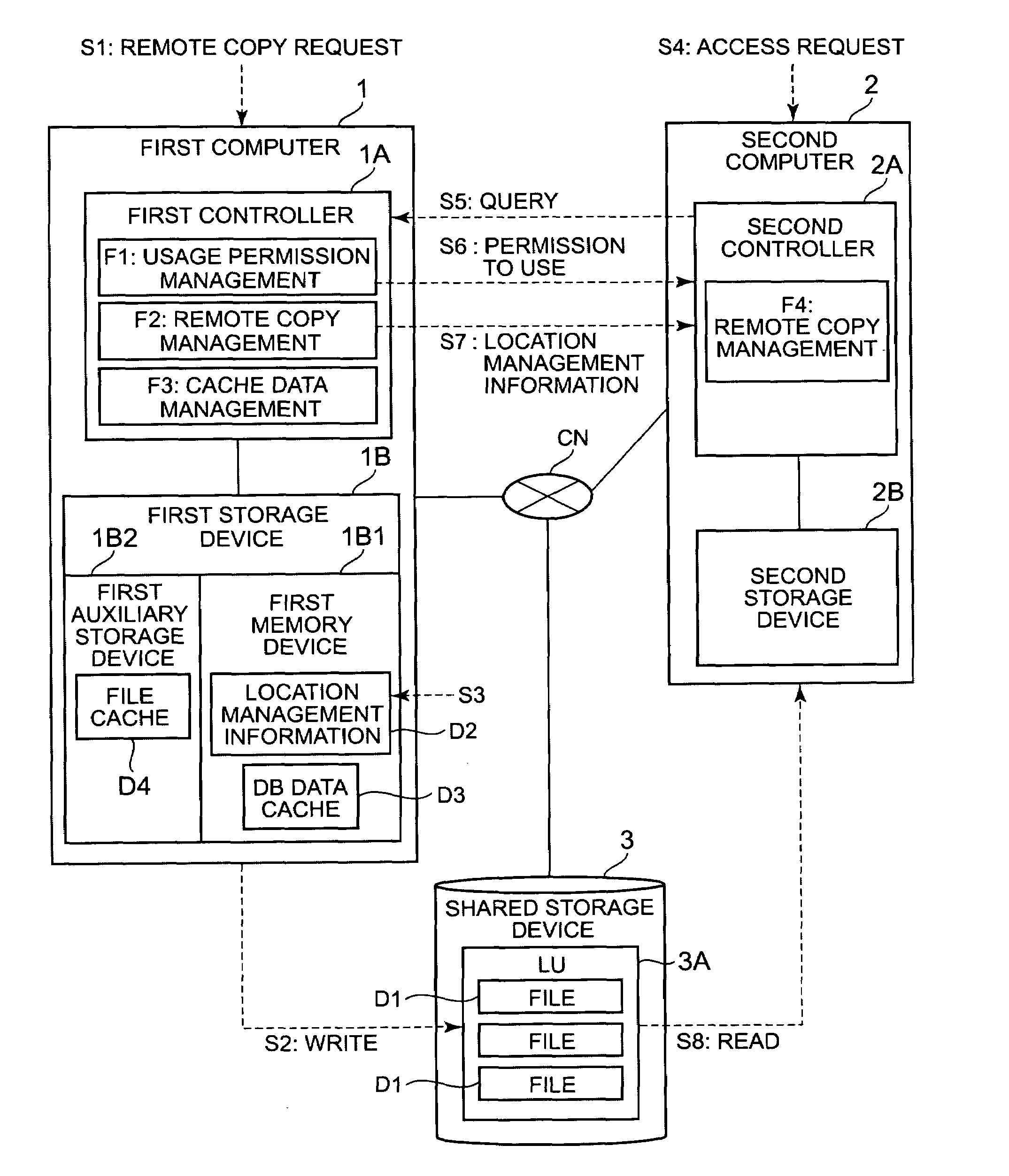
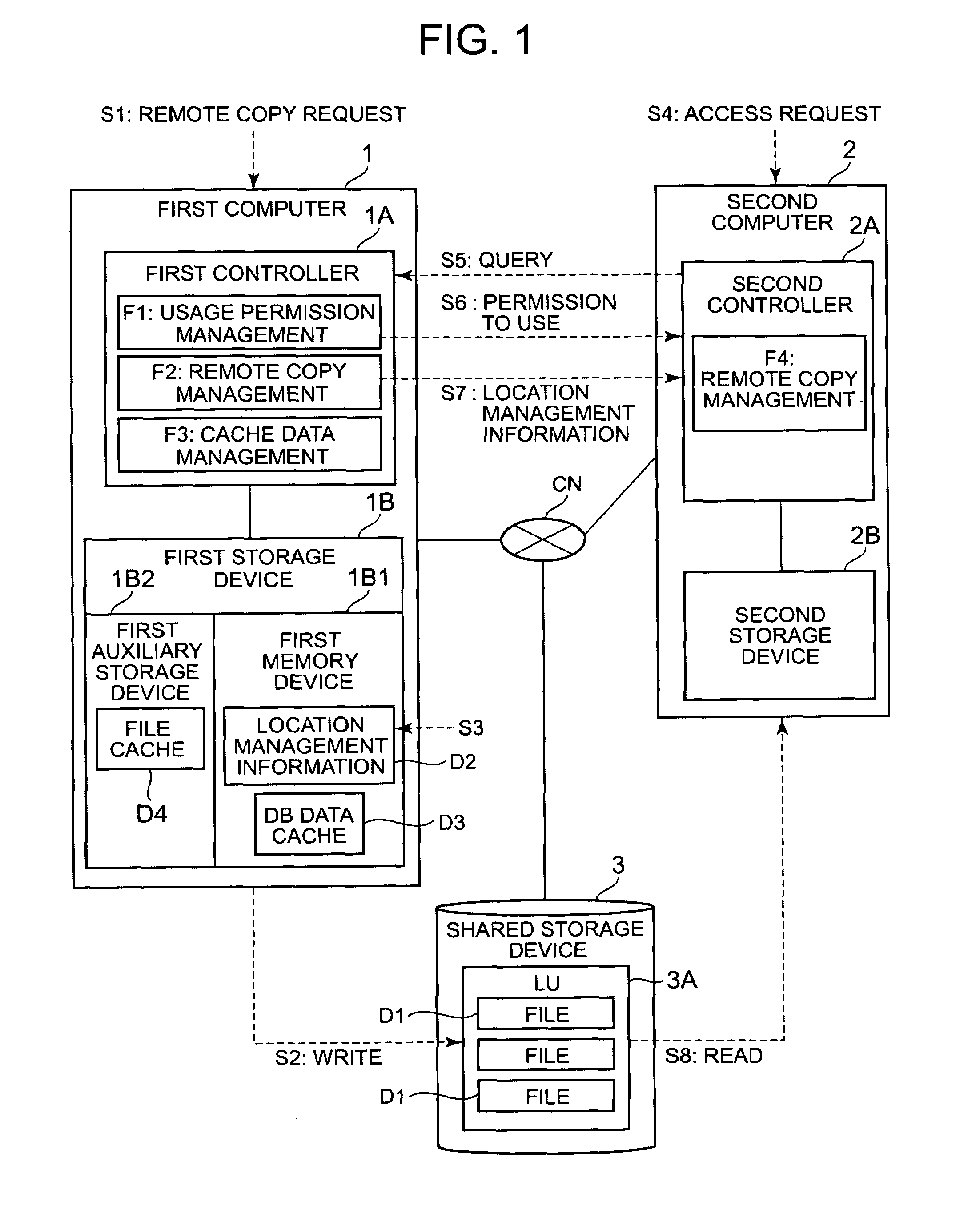
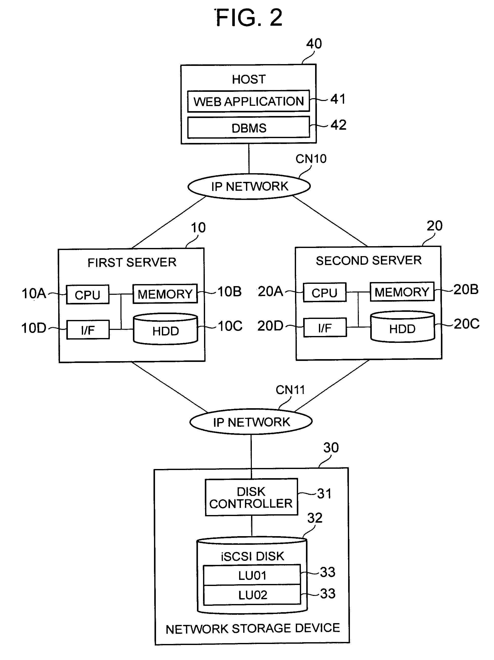
[0090]FIG. 2 is a schematic diagram showing the overall configuration of a computer system related to this embodiment. The corresponding relationship with FIG. 1 will be explained first. A first server 10 corresponds to the first computer 1 of FIG. 1, a second server 20 corresponds to the second computer 2 of FIG. 1, a network storage device 30 corresponds to the shared storage device 3 of FIG. 1, communication networks CN10 and CN11 correspond to the communication network CN of FIG. 1, and a logical volume 33 corresponds to the logical volume 3A of FIG. 1. A connection controller 16 in FIG. 3 corresponds to the usage permission function F1 of FIG. 1, a remote copy manager 12 in FIG. 3 corresponds to remote copy management F2 of FIG. 1, and a cache data manager 13 in FIG. 3 corresponds to cache data management F3 of FIG. 1. A remote copy manager 22 in FIG. 3 corresponds to remote copy management F4 of FIG. 1, a DAS 15 in FIG. 3 corresponds to the first auxiliary storage device 1B2 o...

second embodiment

[0180]A second embodiment will be explained on the basis of FIGS. 16 and 17. The embodiments that follow, to include this embodiment, correspond to variations of the first embodiment. Therefore, explanations that duplicate those given for the first embodiment will be omitted, and the explanation will focus on the characteristic features of this embodiment. In this embodiment, as will be described hereinbelow, cache data management is excluded.

[0181]FIG. 16 is a flowchart of a read process executed by the second server 20. The process comprises all the steps of the respective steps of S60 through S76 shown in FIG. 8, with the exception of steps S61, S62, S69 and S70 related to the management of cache data.

[0182]FIG. 17 is a flowchart of a write process executed by the second server 20. The process comprises all of the respective steps from S90 through S105 shown in FIG. 10, with the exception of steps S91 through S93 related to the management of cache data.

[0183]Thus, the second serv...

third embodiment

[0184]A third embodiment will be explained on the basis of FIG. 18. This embodiment shows a variation of the processing of FIG. 9. FIG. 18 is a flowchart of a remote copy process in accordance with this embodiment. The process comprises all of the respective steps from S80 through S83 shown in FIG. 8. In addition, the process adds a new step S84 between steps S80 and S81.

[0185]In the new step S84, it is determined whether or not the command received from the host 40 prohibits the implementation of the remote copy process (S84). When the command prohibits the remote copy process (S84: YES), the second server 20 ends the processing. The second server 20 does not read out the remote copy target file even when the remote copy target file 34 exists inside the mounted logical volume 33.

[0186]By contrast, when the command received from the host 40 does not prohibit a remote copy process (S84: NO), the second server 20 reads out the remote copy target file 34 from the logical volume 33 (S81...


PUM


Abstract

In a computer system of the present invention, the logical volume of a network storage device can be exclusively shared by a plurality of computers. A first computer, upon receiving a remote copy request, writes a remote copy target file to a logical volume inside a shared storage device, and stores location management information showing the write-destination or the like of the file in a memory device. A second computer, upon receiving an access request, acquires the logical volume lock from the first computer. The second computer mounts the logical volume, and executes the desired processing. Furthermore, the second computer reads out the file from the logical volume based on the location management information.

Description

CROSS-REFERENCE TO PRIOR APPLICATION[0001]This application relates to and claims the benefit of priority from Japanese Patent Application number 2008-017449, filed on Jan. 29, 2008, the entire disclosure of which is incorporated herein by reference.BACKGROUND OF THE INVENTION[0002]1. Field of the Invention[0003]The present invention relates to a computer system, a remote copy method, and a first computer.[0004]2. Description of the Related Art[0005]An iSCSI (Internet Small Computer System Interface), which can make use of SCSI commands utilizing an IP (Internet Protocol) network, has been proposed. In iSCSI technology, an SCSI command, data and so forth are stored in a TCP / IP (Transmission Control Protocol / Internet Protocol) packet and encapsulated. Consequently, a storage device that conforms to iSCSI technology can be directly connected to a communication network, and a computer connected to the communication network can access the storage device to read and write data (JP-A-2005-...

Claims


Application Information

Patent Timeline
IPC IPC(8): G06F15/167G06F12/16
CPCG06F3/0611G06F3/067G06F3/0656G06F3/065
Inventor OGATA, YOUKOSUZUKI, HIDENORI
Owner HITACHI LTD
Learn More