
System, methods and apparatus for waking an autonomous active implantable medical device communicating by pulses transmitted through the interstitial tissues of the body

a technology of implantable medical devices and pulses, applied in the field of medical devices, can solve the problems of requiring a requiring relatively high transmission rate, and requiring relatively high transmission power, and achieve the effect of low latency in response and high responsiveness of leadless capsules

Active Publication Date: 2013-11-05
SORIN CRM
View PDF20 Cites 104 Cited by
  • Summary
  • Abstract
  • Description
  • Claims
  • Application Information

AI Technical Summary

Benefits of technology

[0024]It is, therefore, an object of the present invention to preserve the useful life of a leadless capsule, dependent on an integrated self-powered system. It is another object to provide a leadless capsule that is not likely to be affected by spurious electrical signals present in the body tissues, including the disruption by cardiac myopotentials and other potentials present in the body, or by the stimulation pulses that may be delivered by an implanted device. It is yet another object of the present invention to have a leadless capsule that does not require complex circuits for a sleep implementation and has minimal latency in response to a wake-up pulse, to ensure a high responsiveness of the leadless capsule.

Problems solved by technology

This technique is safe and effective, but it nevertheless has the disadvantage of requiring a relatively high transmission power, given the attenuation of acoustic waves into the body, and allows only relatively low data transmission rates.
This also requires relatively high transmission power, and the attenuation of these waves by intracorporeal tissue is a major barrier to their spread.
Whatever the communication technique used, the processing of the HBC signal collected at the leadless capsule requires significant energy compared to the energy resources available in the leadless capsule.
It is recognized that the communication between a leadless capsule and a remote device is not continuous, and the active circuitry for signal processing (e.g., one or more of signal conditioning, amplification, scanning, filtering, decoding, and signal analysis) is therefore unnecessarily powered, with a negative impact on the autonomy of the leadless capsule and hence its useful lifetime, in the absence of a specific sleep implementation.
On the other hand, if the active circuits of the receiver are in a sleep mode then it becomes impossible to detect the occurrence of a HBC signal.
This technique requires a compromise between a low frequency of wake-ups—which saves energy but reduces the responsiveness—and conversely a higher frequency—which improves responsiveness but only slightly reduces the average energy consumption of the capsule in the long term.
One of the major difficulties of this approach has been the low amplitude level of HBC signals to be detected by the wake-up circuit, given the rapid attenuation of propagating electrical pulses in the interstitial tissues of the body.
Another difficulty is that, the pulses of HBC signals can be mixed with parasitic electrical signals of relatively high level, such as the body's natural myopotentials and the cardiac depolarization waves propagating within the myocardium—hence there is a deteriorated signal / noise ratio.
But in extreme conditions, this attenuation can reach 60 dB, so that the clock signal sent to the leadless capsule is mixed in a background noise, thus having both a very low pulse amplitude to be detected and a very poor signal / noise ratio.

Method used


Image

  • System, methods and apparatus for waking an autonomous active implantable medical device communicating by pulses transmitted through the interstitial tissues of the body
  • System, methods and apparatus for waking an autonomous active implantable medical device communicating by pulses transmitted through the interstitial tissues of the body
  • System, methods and apparatus for waking an autonomous active implantable medical device communicating by pulses transmitted through the interstitial tissues of the body

Examples


first embodiment

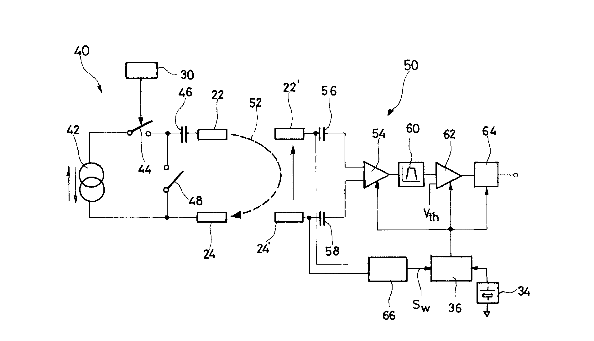
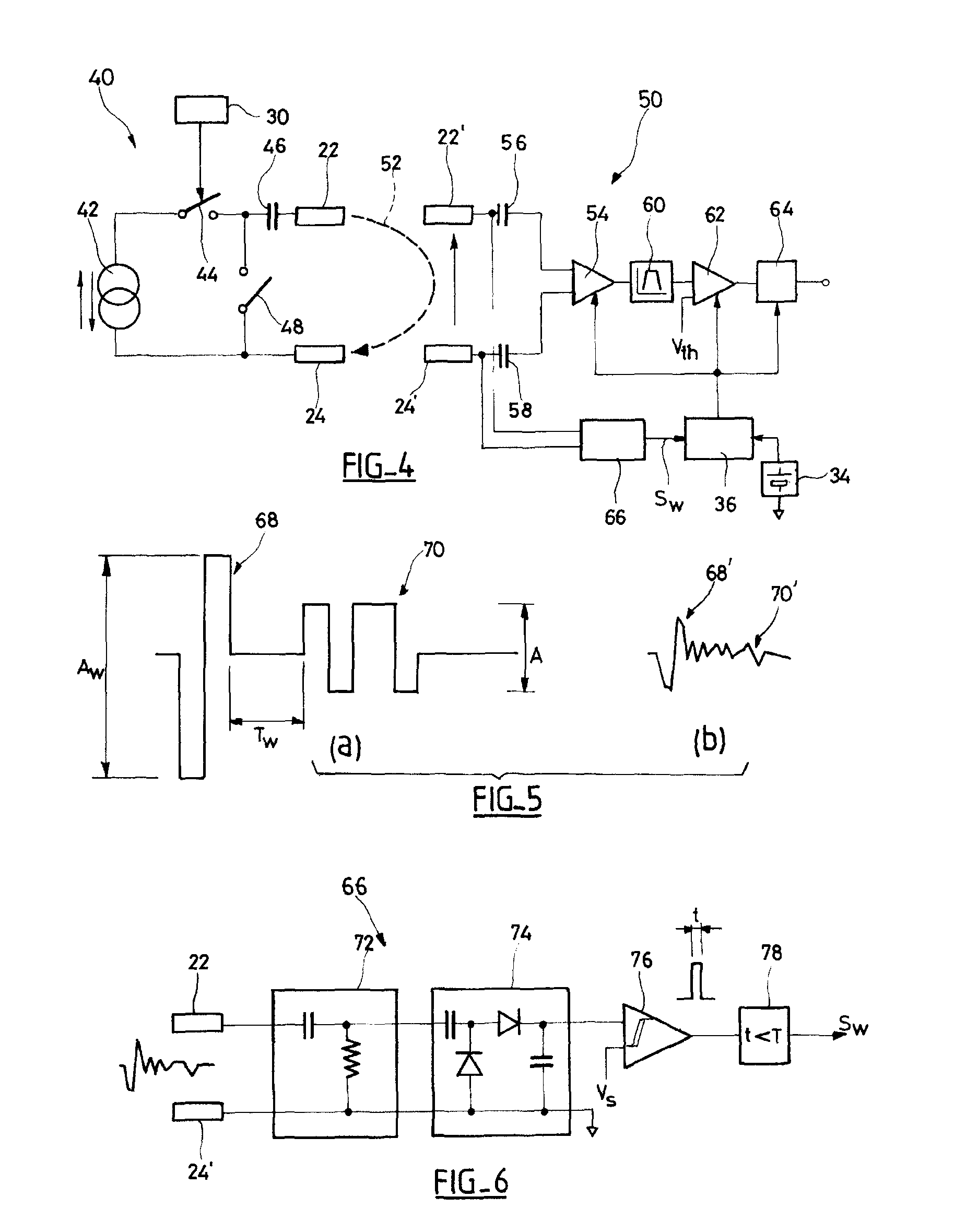
[0071]The first embodiment, illustrated in FIGS. 5 and 6, is optimized for communication channels with low attenuation and a good signal / noise ratio. “Low attenuation” should be understood to mean an attenuation between ×10 and ×100, or between 20 to 40 dB. In this case, a predetermined characteristic pulse pattern, such as that shown in FIG. 5a, including a (biphasic) pulse 68 of high amplitude Aw, is generated, forming a wake-up signal that is used to trigger the wake-up, followed by a succession of (also biphasic) pulses 70 of smaller amplitude A, for the HBC signals to be delivered to the receiver device.

[0072]A biphasic pulse of ±1.5 V (i.e., a peak-to-peak amplitude Aw=3 V) can for example be generated at the transmitter device side, which provides for an attenuation of between 20 and 40 dB, and a pulse having an amplitude between about ±150 mV and ±15 mV, at the receiver device side.

[0073]The received signal corresponding to the transmitted signal is comparable to that illust...

second embodiment

[0093]In this second embodiment, the detection quality of the wake-up signal depends on the duration of a bit and not just of the signal / noise ratio. The number of pulses encoding a bit (n bits to encode a ‘0’ and 2n bits to encode a ‘1’) can thus be increased and increases with the time constant (integration time) of the envelope detector to increase the quality of reception—with a corresponding reduction in the communication flow.

[0094]Again, the circuits of the wake-up circuit of the second embodiment are passive circuits, with the exception of the comparators 92 and 98, whose energy consumption is, however, extremely low, as explained above in connection with the first embodiment.


PUM


Abstract

An autonomous active medical implantable device, with a power supply and a wake-up circuit that responds to receipt of specific pulses transmitted through the interstitial tissues of the body. A transmitter device (40) generates trains of modulated pulses applied to electrodes (22, 24), and a receiver (50) processes (e.g., filter, amplify and demodulate) pulses collected on electrodes (22′, 24′). The receiver circuits (50) are selectively activated from a dormant (sleep) state in which they are not powered by a power source (34), to an operational (active) state in which they are powered and able to process (e.g., filter, amplify and demodulate) the collected pulses. A specific wake-up pulse train, configured in a predetermined characteristic pulse pattern, triggers passive wake-up circuits (66) in the receiver (50) to switch the receiver circuits from the sleep state to the operational state.

Description

RELATED APPLICATIONS[0001]The present application claims the benefit of French Application No. 10 / 58476 entitled “Autonomous active medical implant, with a wake-up circuit of the power supply on receipt of pulses transmitted through the interstitial tissues of the body” and filed Oct. 18, 2010, which is hereby incorporated by reference in its entirety.FIELD OF THE INVENTION[0002]The present invention relates to “medical devices” as defined by the 14 Jun. 1993 Directive 93 / 42 / EEC of the Council of the European Communities, including the “active implantable medical devices” as defined by the 20 Jun. 1990 Directive 90 / 385 / EEC of the Council of the European Communities, more particularly, to devices that continuously monitor a patient's cardiac rhythm and deliver if necessary to the patient's heart electrical pulses for stimulation, resynchronization, cardioversion and / or defibrillation in response to a cardiac rhythm disorder detected by the device, and to neurological devices, cochlea...

Claims


Application Information

Patent Timeline
Patent Type & Authority Patents(United States)
IPC IPC(8): H04B1/16H04K3/00
CPCA61N1/37288A61B5/0028A61N1/37217A61N1/37276
Inventor MAKDISSI, ALAAAMARA, KARIMAGHILDIYAL, ASHUTOSH
Owner SORIN CRM
Learn More