
Client-server visualization system with hybrid data processing

a visualization system and client server technology, applied in the field of digital data processing, can solve the problems of long wait times for users during transfer, high computational intensity of rendering such images, and long time on a standard computer, so as to improve application responsiveness and render speed on the client computer

Active Publication Date: 2009-08-20
PME IP
View PDF7 Cites 104 Cited by
  • Summary
  • Abstract
  • Description
  • Claims
  • Application Information

AI Technical Summary

Benefits of technology

The invention is a system that allows for simultaneous connection of multiple client computers to a render server for image processing. The client computers generate messages that cause the render server to render images and return the results for display or further processing. The system improves rendering speed and application responsiveness by performing certain operations either on the server or the client, based on their respective strengths. The client computers can have local processing resources, such as a CPU or GPU, for faster processing. The system combines aspects of the image rendered by the render server with those rendered by the client computer, and can make the combined image available for further processing and display. The system also allows for interleaved requests from the client computers and maintains requests in queues on the render server. The technical effects of the invention include improved rendering speed and responsiveness, as well as flexibility and adaptability for different user needs.

Problems solved by technology

The rendition of such images can be quite compute intensive and therefore takes a long time on a standard computer, especially, when the data sets are large.
Second the data sets often need to be transferred from a central store (e.g., a main enterprise server), where they are normally stored, to those local workstations prior to analysis and visualization, thus potentially causing long wait times for the user during transfer.
However, most of these solutions do not allow applications to use graphics hardware acceleration.
However that pipeline could then not be used locally any longer and was also blocked for other users.
While such a solution is transparent to the application and therefore convenient for the application developers it is very limited too.

Method used


Image

  • Client-server visualization system with hybrid data processing
  • Client-server visualization system with hybrid data processing
  • Client-server visualization system with hybrid data processing

Examples


Embodiment Construction

[0030]The construction and operation of the illustrated embodiment may be more fully appreciated by reference to co-pending, commonly assigned U.S. patent application Ser. No. 12 / 275,421, Attorney Docket 109006-273, filed this same day herewith, by the same inventors named above, entitled “multi-User multi-GPU Render Server Apparatus and Methods” (hereinafter, the “Related Application”), a non-provisional claiming the benefit of filing of U.S. Provisional Patent Application Ser. No. 60 / 989,881, entitled “multi-User multi-GPU Render Server Apparatus and Methods,” the teachings of both which are incorporated by reference herein. A copy of the Related Application is attached as an Appendix hereto.

[0031]Overview

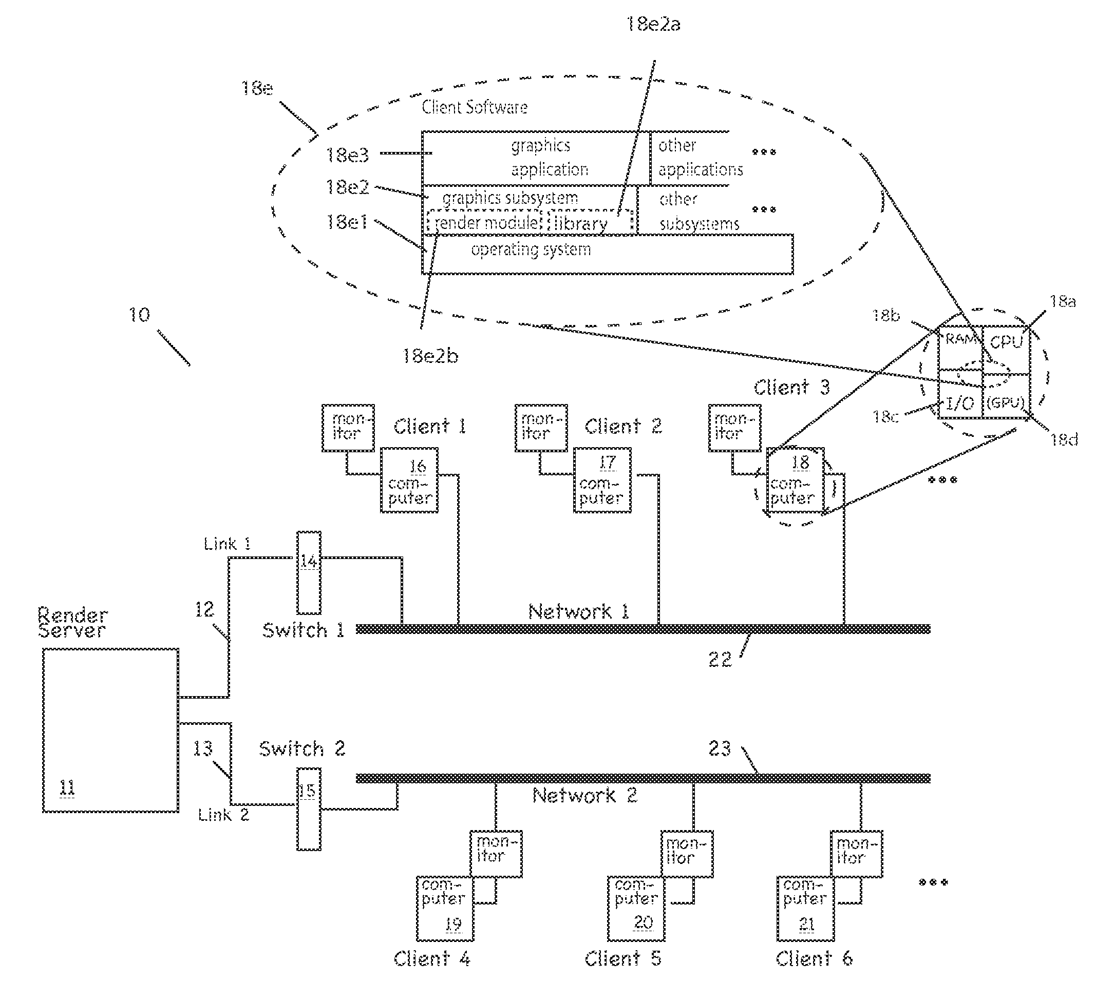
[0032]FIG. 1 depicts a system 10 according to one practice of the invention. A render server, or server digital data processor, 11 is connected via one or more network interfaces 12, 13 and network devices, such as switches or hubs 14, 15, to one or more networks 22, 23—which can...


PUM


Abstract

The invention comprises a system of client-server visualization with hybrid data processing, having a server digital data processor, that allows for server side rendering and processing image data, and client digital data processors simultaneously connected to the server, which receives messages from the clients, creates rendered images of data sets or other data processing results and sends those rendered images and results to the clients for display or further processing. Performing certain image rendering operations on either the server or the client according to which is better suited for the tasks requested by the user at any point in time, and possibly adjusting this division of work dynamically, improves rendering speed and application responsiveness on the clients.

Description

BACKGROUND OF THE INVENTION[0001]This application claims the benefit of priority of U.S. Patent Application Ser. Nos. 60 / 989,881 and 60 / 989,913, both filed Nov. 23, 2007, the teachings of both of which are incorporated herein by reference.[0002]The invention pertains to digital data processing and, more particularly, by way of example, to the visualization of 3D and 4D image data. It has application to areas including, by way of non-limiting example, medical imaging, atmospheric studies, astrophysics, and geophysics. 3D and 4D image data is routinely acquired with computer tomographic scanners (CT), magnetic resonance imaging scanners (MRI), confocal microscopes, 3D ultrasound devices, positron emission tomographic scanners (PET) and other imaging devices. Medical imaging is just one example of a market that uses these devices. It is growing rapidly, with new CT scanners, for example, collecting ever greater amounts of data even more quickly than previous generation scanners. As thi...

Claims


Application Information

Patent Timeline
Patent Type & Authority Applications(United States)
IPC IPC(8): G06F15/16G06T1/00G06T15/00
CPCG06T15/005G06T15/00G09G5/363G09G5/001G09G5/006G09G5/395G09G2360/12G09G2360/18G09G2370/022
Inventor WESTERHOFF, MALTESTALLING, DETLEV
Owner PME IP
Learn More