Impact tool and method of controlling impact tool
a technology of impact tool and impact force, which is applied in the direction of screwdrivers, power driven tools, wrenches, etc., can solve the problems of reducing operation efficiency, increasing the risk of screw damage, and increasing the time required for the entire fastening process, so as to reduce the size of the tool, increase the rotational speed, and reduce the effect of fastening torqu
- Summary
- Abstract
- Description
- Claims
- Application Information
AI Technical Summary
Benefits of technology
Problems solved by technology
Method used
Image
Examples
first embodiment
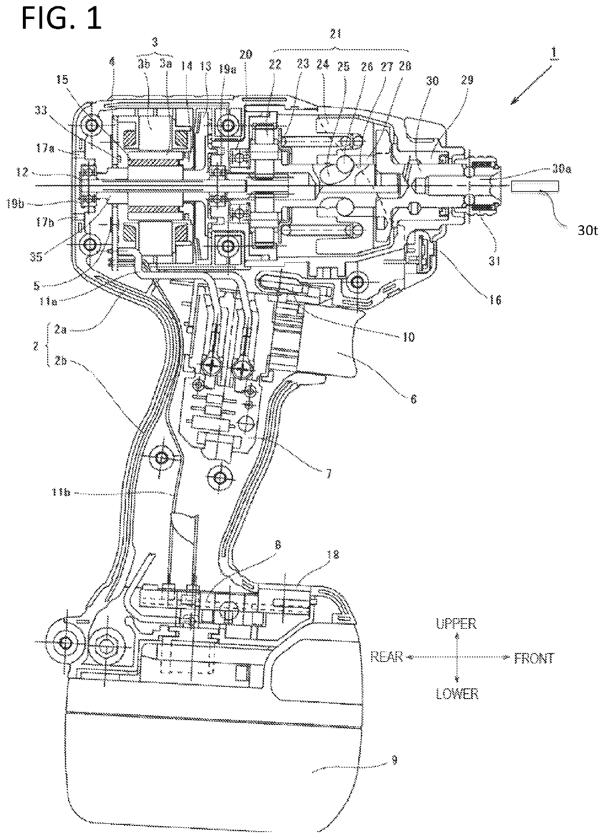
[0057]Hereinafter, an illustrative embodiment of the present invention will be described with reference to the accompanying drawings. In the following description, a front-rear direction and an upper-lower direction are referred to the directions indicated by arrows of FIG. 1.
[0058]FIG. 1 is a view showing an internal structure of an impact tool 1 according to the present invention. The impact tool 1 is powered by a rechargeable battery 9 and uses a motor 3 as a driving source to drive a rotary striking mechanism 21. The impact tool 1 applies a rotating force and a striking force to an anvil 30 which is an output shaft. The impact tool 1 intermittently transmits a rotational striking force to a tip tool 31t such as a driver bit to fasten a screw or a bolt. Here, the tip tool is held on an mounting hole 30a of a sleeve 31. The brushless DC type motor 3 is accommodated in a cylindrical main body 2a of a housing 2 which is substantially T-shaped, as seen from the side. A rotating shaft...
second embodiment
[0078]Next, a second embodiment of the present invention will be described with reference to FIG. 7 to FIG. 9. Similarly to the first embodiment, the second embodiment has a configuration that the high duty ratio is lowered just before the first striking is performed. However, in the second embodiment, control is made in such a way that the duty value is gradually increased at a predetermined rate after the duty ratio is lowered to a low duty ratio and while the motor current is maintained in a state of being equal to or less than the current threshold I1.
[0079]Now, relationship among the motor current, the duty ratio of PWM drive signal and the fastening torque in the impact tool of the second embodiment will be described by referring to FIG. 7. In each graph of (1) to (3) of FIG. 7, a horizontal axis represents time (in milliseconds) and each horizontal axis is commonly represented. The present embodiment illustrates an example where a short screw is fastened using the impact tool...
third embodiment
[0084]Next, a third embodiment of the present invention will be described with reference to FIG. 10 and FIG. 11. In the third embodiment, a control for returning the duty ratio from the low duty ratio to the high duty ratio is added to the first embodiment. FIG. 10 shows relationship among the motor current, the duty ratio of PWM drive signal and the fastening torque in the impact tool of fastening a long screw. First, when rotation of the motor 3 is started at time t0, a motor current 131 is abruptly increased as in an arrow 131a in accordance with the fastening situation of the screw and exceeds the current threshold I1 at time t1. Therefore, the operation unit 40 decreases the PWM duty ratio from 100% to 40%. However, thereafter, the motor current 131 reaches a peak as in an arrow 131c and then is rapidly decreased as in an arrow 131d whereby the motor current is often less than a return current threshold (third threshold) IR. This is a phenomenon that the motor current value I i...
PUM
 Abstract
Description
Claims
Application Information
 - R&D
- Intellectual Property
- Life Sciences
- Materials
- Tech Scout
- Unparalleled Data Quality
- Higher Quality Content
- 60% Fewer Hallucinations
Browse by: Latest US Patents, China's latest patents, Technical Efficacy Thesaurus, Application Domain, Technology Topic, Popular Technical Reports.
© 2025 PatSnap. All rights reserved.Legal|Privacy policy|Modern Slavery Act Transparency Statement|Sitemap|About US| Contact US: help@patsnap.com


