
Liquid crystal, display device, driving method therefor and electronic equipment

Inactive Publication Date: 2005-10-06
SHARP KK
View PDF23 Cites 110 Cited by
  • Summary
  • Abstract
  • Description
  • Claims
  • Application Information

AI Technical Summary

Benefits of technology

[0011] In view of the above, a main object of the present invention is providing an alignment-divided vertical alignment LCD permitting high quality moving image display, a driving method therefor, and electronic equipment provided with such an LCD.
[0035] According to the present invention, the width of the liquid crystal regions is set to fall in a predetermined range, so that occurrence of a unique behavior (“alignment deflection” to be described later) of liquid crystal molecules in an alignment-divided vertically aligned LCD can be suppressed. Hence, the response characteristic is improved and the quality of moving image display can be enhanced.

Problems solved by technology

The TN LCD however has a problem of being large in visual angle dependence that results from the alignment of liquid crystal molecules.
This decrease in response speed due to this phenomenon found by the present inventors is not improved with the OS driving and causes degradation in display quality.

Method used


Image

  • Liquid crystal, display device, driving method therefor and electronic equipment
  • Liquid crystal, display device, driving method therefor and electronic equipment
  • Liquid crystal, display device, driving method therefor and electronic equipment

Examples


Embodiment Construction

[0077] Hereinafter, LCDs of embodiments of the present invention and driving methods for the LCDs will be described with reference to the relevant drawings.

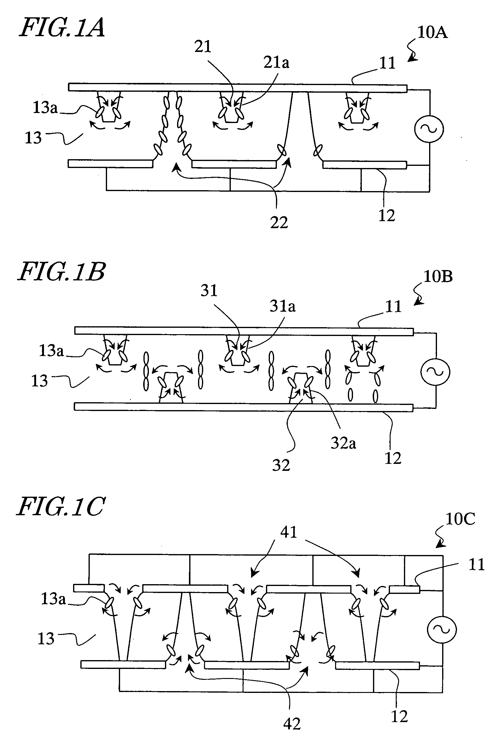
[0078] First, basic constructions of alignment-divided vertical alignment LCDs of embodiments of the present invention will be described with reference to FIGS. 1A to 1C.

[0079] Alignment-divided vertical alignment LCDs 10A, 10B and 10C include a plurality of pixels each having a first electrode 11, a second electrode 12 facing the first electrode 11, and a vertical alignment liquid crystal layer 13 placed between the first electrode 11 and the second electrode 12. The vertical alignment liquid crystal layer 13 includes liquid crystal molecules having negative dielectric anisotropy that are aligned roughly vertical (for example, at an angle in the range between 87° and 90°) to the plane of the first and second electrodes 11 and 12 during non-voltage application. Typically, this alignment is attained by providing a vertical align...


PUM


Abstract

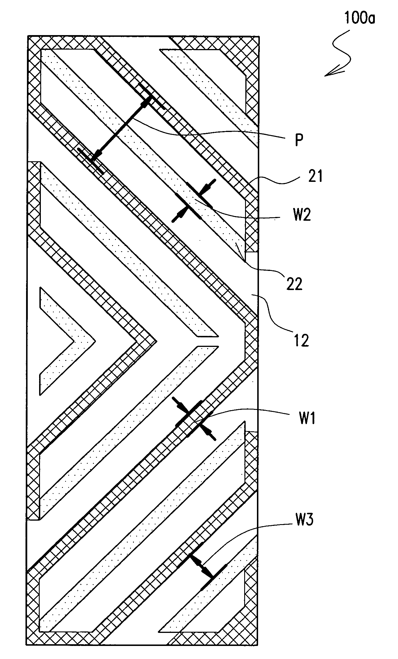
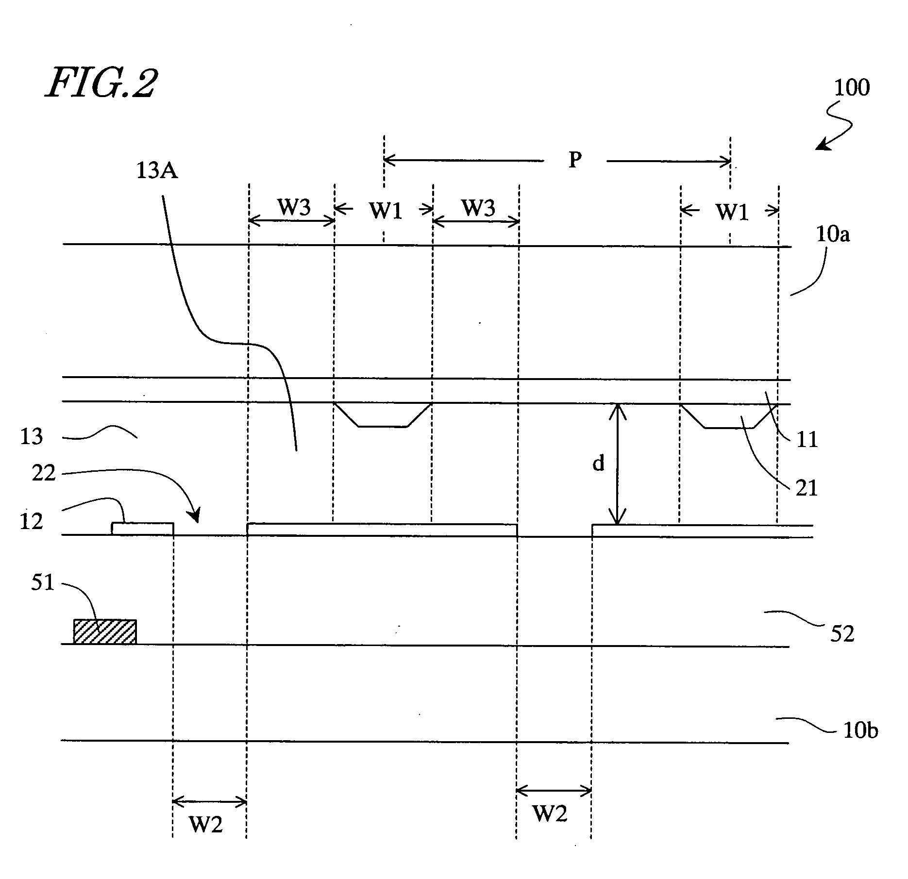
The liquid crystal display device of the invention includes a plurality of pixels each having a first electrode, a second electrode facing the first electrode, and a vertically aligned liquid crystal layer placed between the first and second electrodes. The device further includes stripe-shaped first alignment regulating means having a first width placed in the first electrode side of the liquid crystal layer; stripe-shaped second alignment regulating means having a second width placed in the second electrode side of the liquid crystal layer; and a stripe-shaped liquid crystal region having a third width defined between the first and second regulating means. The third width is in a range between 2 μm and 15 μm.

Description

BACKGROUND OF THE INVENTION [0001] 1. Field of the Invention [0002] The present invention relates to a liquid crystal display device and a driving method for the same, and more particularly relates to a liquid crystal display device suitably used for display of moving images, a driving method for the same, and electronic equipment provided with such a liquid crystal display device. [0003] 2. Description of the Related Art [0004] In recent years, liquid crystal display devices (LCDs) have increasingly come into widespread use. Among various types of LCDs, mainstream has been a TN LCD in which a nematic liquid crystal material having positive dielectric anisotropy is twisted. The TN LCD however has a problem of being large in visual angle dependence that results from the alignment of liquid crystal molecules. [0005] To improve the visual angle dependence, alignment-divided vertical alignment LCDs have been developed, and use of these LCDs is expanding. For example, Japanese Patent Gaz...

Claims


Application Information

Patent Timeline
IPC IPC(8): G02F1/133G02F1/1333G02F1/1337G02F1/1343G09G3/36
CPCG02F1/133707A01K85/14
Inventor KUBO, MASUMINAKAMURA, HISAKAZUOHGAMI, HIROYUKIYAMAMOTO, AKIHIROKAWAMURA, TADASHIOCHI, TAKASHINARUSE, YOHICHI
Owner SHARP KK
Learn More