
Method for Improving Resistance to CMAS Infiltration

Inactive Publication Date: 2009-07-02
GENERAL ELECTRIC CO
View PDF16 Cites 33 Cited by
  • Summary
  • Abstract
  • Description
  • Claims
  • Application Information

AI Technical Summary

Benefits of technology

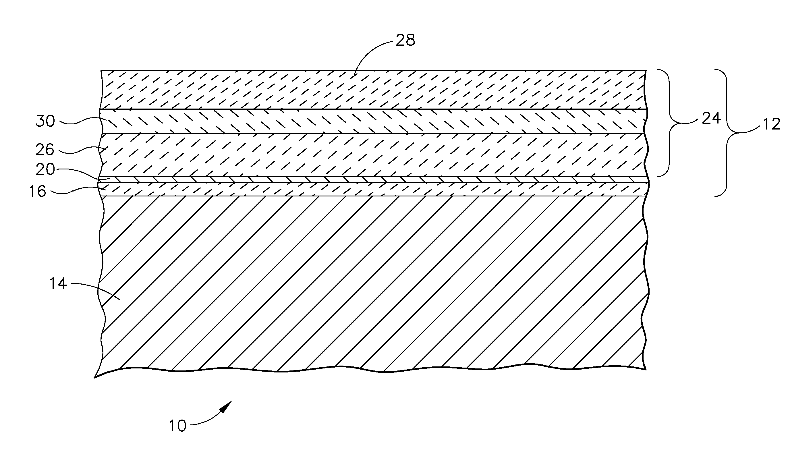
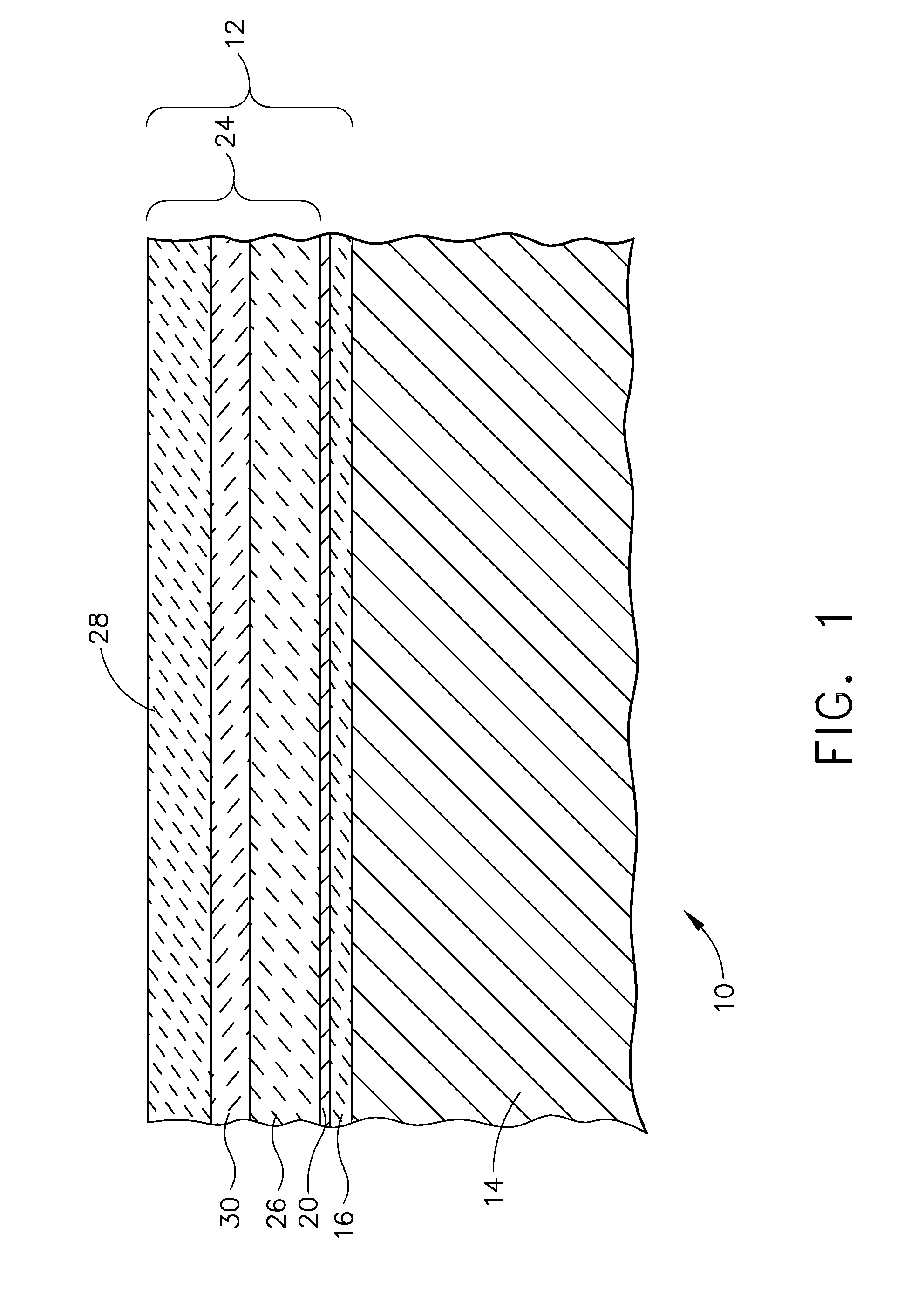
[0008]Exemplary embodiments disclosed herein provide methods for improving resistance to CMAS infiltration of a thermal barrier coating system. An exemplary method includes providing a substrate having at least one surface, depositing a bond coat on the substrate surface, and optionally, subjecting the bond coat to suitable conditions to form a thermally grown oxide layer on th

Problems solved by technology

Under service conditions, these thermal barrier-coated hot section engine components can be susceptible to various modes of damage, including erosion, oxidation and corrosion from exposure to the gaseous products of combustion, foreign object damage and attack from environmental contaminants.
These environmental contaminants are in addition to the corrosive and oxidative contaminants that result from the combustion of fuel.
At the operating temperature of the engine, these contaminants can form contaminant compositions on the thermal barrier coatings.
This infiltration by the liquid CMAS destroys the compliance of the TBC, leading to premature spallation of the TBC.
In addition to the compliant loss, deleterious chemical reactions with yttria and zirconia within the TBC, as well as with the thermally grown oxide at the bond coating / TBC interface, occur and result in a degradation of the coating system.
The spallation due to CMAS infiltration has become a greater problem in jet engines as their operating temperatures have increased to improve efficiency, as well as in engines operating in the Middle East and in coastal regions.
And of course, spallation of the TBC due to exposure to CMAS at elevated temperature only sets the stage for more serious problems.
Continued operation of the engine once the passive thermal barrier protection has been lost leads to rapid oxidation of the base metal superalloy protective coating and the ultimate failure of the component by burn through or cracking.
In fact, such significant distress has been observed in both military and commercial engines.

Method used


Image

  • Method for Improving Resistance to CMAS Infiltration
  • Method for Improving Resistance to CMAS Infiltration
  • Method for Improving Resistance to CMAS Infiltration

Examples


example

[0032]A single phase rare earth aluminate sample (LaAlO3) was exposed to CMAS at 2500° F. ((1371° C.)) for 1 hour. The micrograph shown in FIG. 2 illustrates the reaction products. LaAlO3 reacts with CMAS to form a La calcium silicate phase (needle-like shapes). Energy dispersive spectrometer (EDS) analysis showed that the Al2O3 content in the post reaction CMAS is much higher than in the original CMAS, an indication of Al2O3 component from LaAlO3 dissolution in the original CMAS. The dissolution of Al2O3 in CMAS leads to a CMAS melting point increase, as demonstrated by the CMAS / Al2O3 differential thermal analysis (DTA) curves in FIG. 5.

[0033]Thus, this example demonstrates that a rare earth aluminate containing TBC top layer provides CMAS protection in the high temperature range by the formation of the sealing reaction layer containing rare earth calcium silicate, and in the low temperature range (where rare earth calcium silicate formation is sluggish) by the CMAS melting point i...


PUM

PropertyMeasurementUnit
Lengthaaaaaaaaaa
Lengthaaaaaaaaaa
Lengthaaaaaaaaaa

Abstract

Methods for providing improved resistance to CMAS infiltration for hot section components of a gas turbine engine. Exemplary methods include coating a substrate with a thermal barrier coating system by overlying a bond coated substrate with an inner thermal barrier layer comprised of a thermal barrier material such as yttria-stabilized zirconia. A top layer, including a rare-earth aluminate, is deposited so as to overlie at least a portion of the inner layer. Deposition processes and coating thicknesses may be tailored to the type of component to be coated.

Description

FIELD OF THE INVENTION[0001]The present invention is directed to a multilayer coating system for hot section turbine components, and more specifically to a multilayer coating that includes rare earth elements and coated articlesBACKGROUND OF THE INVENTION[0002]Calcium-magnesium-aluminum-silicate (CMAS) infiltration is a phenomenon that is linked to thermal barrier coating (TBC) spallation in hot section turbine components.[0003]Thermal barrier coatings are utilized on hot section engine components including combustor section and turbine section components to protect the underlying base materials from high temperatures as a result of the flow of hot gases of combustion through the turbine. These hot gases of combustion can be above the melting point of the base materials, which typically are superalloy materials, being based on iron, nickel, cobalt and combinations thereof. The thermal barrier coatings provide passive protection from overheating, and are used in conjunction with cool...

Claims


Application Information

Patent Timeline
IPC IPC(8): B05D3/00B05D7/00
CPCC23C4/02Y02T50/67C23C28/321C23C28/36C23C28/325C23C28/345C23C28/3455C23C28/3215C23C4/04C23C28/00Y02T50/60
Inventor FU, MINGDAROLIA, RAMGOPALGORMAN, MARKNAGARAJ, BANGALORE ASWATHA
Owner GENERAL ELECTRIC CO
Learn More