
Method and device for determining specific heat capacity

a technology of specific heat capacity and heat transfer rate, which is applied in the direction of heat measurement, material heat development, instruments, etc., can solve the problems of inhomogeneity of samples, high labor intensity, and high labor intensity of labor intensity, and achieve the effect of great accuracy

Active Publication Date: 2009-06-18
METTLER TOLEDO GMBH
View PDF7 Cites 19 Cited by
  • Summary
  • Abstract
  • Description
  • Claims
  • Application Information

AI Technical Summary

Benefits of technology

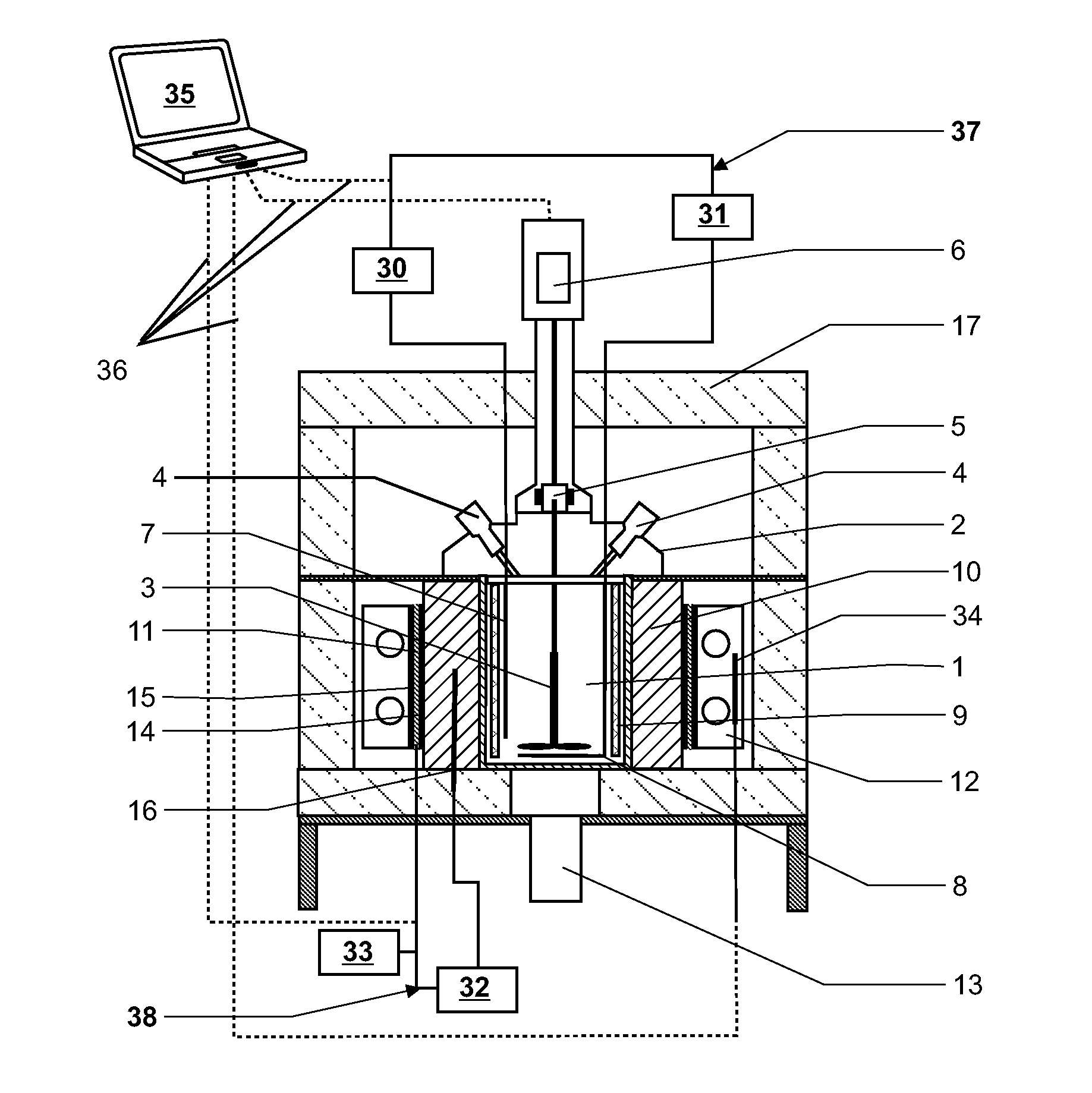
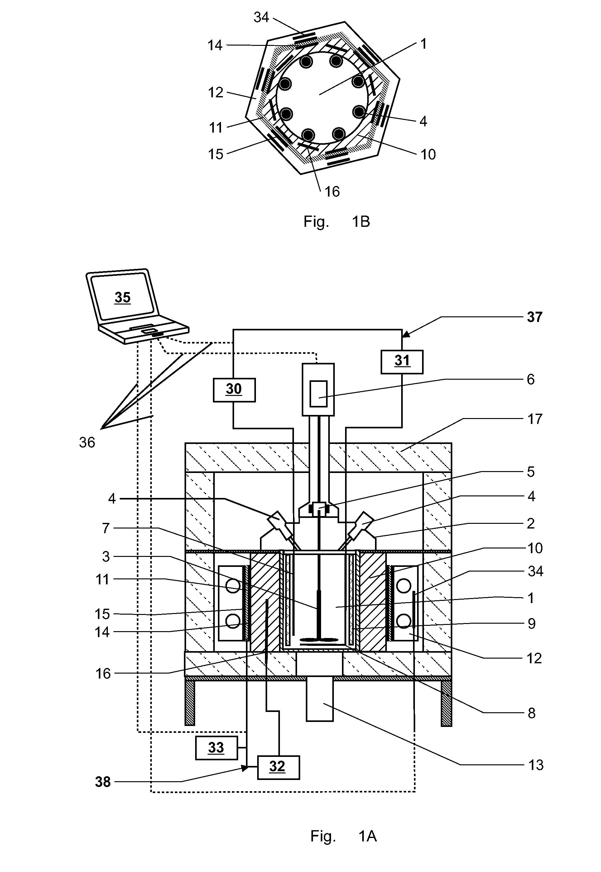
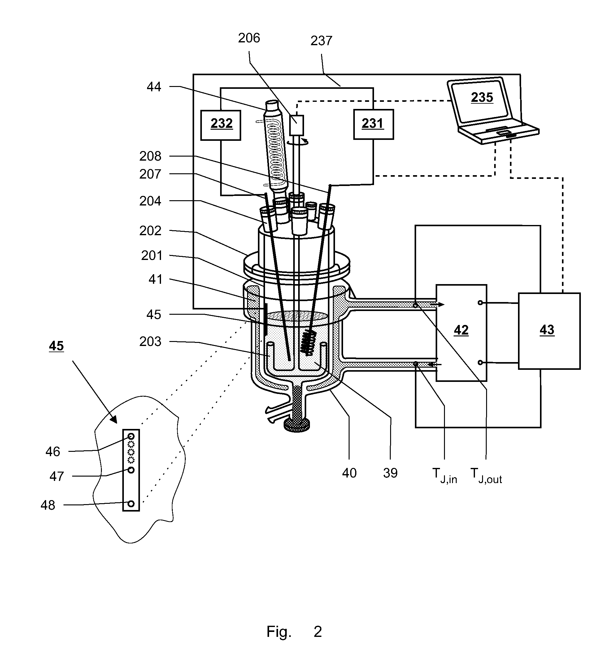
[0010]The term near isothermal refers to the fact, that the medium is maintained at isothermal conditions as long as no modulated energy profile is applied and as the chosen amplitude for the modulated energy profile is very small the system is only slightly disturbed and still behaves nearly isothermally when the modulation is applied. The calorimeter comprises at least two thermostats and can preferably be operated by a combination of heat flow and power compensation principles. This combination is very advantageous and allows the independent determination of an inner and an outer heat balance. The inner heat balance of the reactor and the outer heat balance related to the means for providing the outer heat balance can be determined independently from each other. Therefore, it is possible to determine the overall heat transfer coefficient UA directly and independently from the specific heat capacity of the medium cp without relying on any calibration. The overall heat transfer coefficient UA as well as the specific heat capacity of the medium cp can be determined continuously throughout an experiment and even while performing a chemical or physical reaction. The determination of UA and cp can, if desired, be performed continuously or at predefined time intervals which allows to monitor changes of the overall heat transfer coefficient UA as well as of the total heat capacity of the medium Cp,m. Furthermore, the medium under investigation can be stirred continuously by a stirrer arranged in the reactor in order to provide a homogeneous mixed medium as well as a homogeneous heat and / or energy distribution in the medium which enhances the accuracy of the measuring results.
[0016]When the modulated energy profile is applied to the medium, it also influences other components of the calorimeter, which start to exhibit a similar modulation as answer to the modulation applied to the medium. These resulting energy changes relating to the medium and / or any of the thermostats can be determined directly and / or indirectly by at least one temperature sensor, at least one power meter and / or at least one heat flow sensor. Preferably the resulting energy changes of each component are determined separately by one or by a plurality of the mentioned devices or a combination of said devices. The determination of the heat capacity relies on heat or power values, which can be easily derived from temperature values or be directly measured by heat flow sensors.
[0021]The first thermostat, in particular a compensation heater, can be arranged inside the reactor in direct contact with the medium. In that case, in particular when the first thermostat has short response times, it is advantageous to superimpose the energy provided by the first thermostat with the modulated energy profile.

Problems solved by technology

Calorimetric experiments are easy to conduct but harbor several drawbacks concerning the accuracy of the obtained data.
Additionally, such experiments can be very time consuming.
Additionally, inhomogenities can occur in the sample, as this is placed in a small cup without stirring.
These inhomogenities can have a negative impact on the experimental results.
This technique is also prone to inhomogenities and in particular to local inhomogenities in the sample, which have a negative impact on the results.
Especially, the precise and timely control of the thermostat presents a difficulty, as some of the common heat carriers show a delayed reaction on temperature changes.

Method used


Image

  • Method and device for determining specific heat capacity
  • Method and device for determining specific heat capacity
  • Method and device for determining specific heat capacity

Examples


example 1

[0077]In a first experiment the reactor was filled with 34 ml of water. The jacket temperature TJ was set to 17° C. and the temperature of the heat exchanger to 15° C. Both temperatures were kept at a constant value throughout the experiments. The stirrer speed was 500 rpm.

[0078]The reaction temperature Tr was superimposed with a modulated energy profile in form of an oscillating set-temperature provided by the compensation heater. This modulation resulted in a reaction temperature profile of

Tr=25+0.5·cos(t120)[°C.],[12]

with t being the time constant expressed in seconds [s]. This modulated temperature profile corresponds to an oscillating period of about 2 min and an amplitude of about ±0.5° C. The amplitude can vary slightly due to a delay in the response time of the temperature controller of the compensation heater. In the case of the calorimeter described in FIG. 1 it equals about ±0.52° C.

[0079]For simulating a reaction and providing a power due to dosing additional water was a...

example 2

[0090]In a second experiment the reactor was first filled with 25 ml of water and the temperature of the reactor Tr was set to 25° C. A step function was then applied to the compensation heater qcomp as modulated energy profile. Each step comprised an increase in reaction temperature Tr of 0.8° C. and lasted for about 10 minutes.

[0091]The jacket temperature TJ was set to 20° C. and the temperature of the heat exchanger to 10° C. After 60 min, water was added with a flow rate of 0.125 ml / min until a total volume of 50 ml was reached after 260 min. The stirrer speed was set to 500 rpm.

[0092]The total heat capacities have been calculated every 20 minutes.

[0093]In case of the step function, the modulation can be expressed as:

X~i=Xi,0+∑n=1jBi,nexp(-λi,n·t)[16]

where j is the order of the signal i. It could be determined experimentally that for the calorimeter and the experiment described above the order equals j=1 and equation 16 can be rewritten as:

Xi=Xi,0+Bi,1exp(−λi,1·t)  [17]

[0094]As ...


PUM


Abstract

The specific heat capacity (cp) of a medium is determined using a calorimeter with a reactor (1), a stirrer (3), a first thermostat for providing an inner heat balance, a second thermostat, means for providing an outer heat balance and a central control unit (35). The method uses the steps of: applying a modulated energy profile to the medium, inside the reactor (1), under near isothermal conditions; monitoring the resulting energy changes of: the medium, the reactor (1), the first thermostat, the second thermostat and / or the outer heat balance means as a function of time; determining the respective inner and outer heat balances independently from each other at predefined time intervals; and calculating the overall heat transfer coefficient (UA) and the specific heat capacity of the medium (cp) simultaneously and independently from each other as a function of time from the inner and outer heat balances.

Description

CROSS-REFERENCE TO RELATED APPLICATIONS[0001]This application is a continuation under 35 USC §120 of PCT / EP2007 / 007143, filed 13 Aug. 2007, which is in turn entitled to benefit of a right of priority under 35 USC §119 from European patent application 06 01 6978.6, filed 15 Aug. 2006, the contents of each of which is incorporated by reference as if fully recited herein.TECHNICAL FIELD[0002]The invention concerns the determination of the specific heat capacity cp of a sample or medium arranged inside a temperature controlled reactor, such as a calorimeter reactor.BACKGROUND OF THE ART[0003]The heat capacity Cp is a thermo-physical property. The heat capacity of a medium as well as the heat capacities of different parts of a setup has to be known for scale-up processes, reactor design as well as for safety assessments. The heat capacity of a medium or of a sample, e.g. a fluid, is often determined with calorimetric methods, which comprise the application of a specific temperature profi...

Claims


Application Information

Patent Timeline
IPC IPC(8): G01K17/00G06F15/00
CPCG01N25/005
Inventor RICHNER, GILLESHUNGERBUEHLER, KONRADSCHENKER, BENEDIKT
Owner METTLER TOLEDO GMBH
Learn More