Method for manufacturing photoelectric conversion device
a technology of photoelectric conversion and manufacturing method, which is applied in the manufacture of final products, basic electric elements, climate sustainability, etc., can solve the problems of reducing the revenues of the production plant for solar cells, the sourcing cost of silicon wafers is increased, and the supply cannot meet the demand. , to achieve the effect of improving conversion efficiency and reducing the surface reflectivity of single crystal semiconductor layers
- Summary
- Abstract
- Description
- Claims
- Application Information
AI Technical Summary
Benefits of technology
Problems solved by technology
Method used
Image
Examples
embodiment mode 1
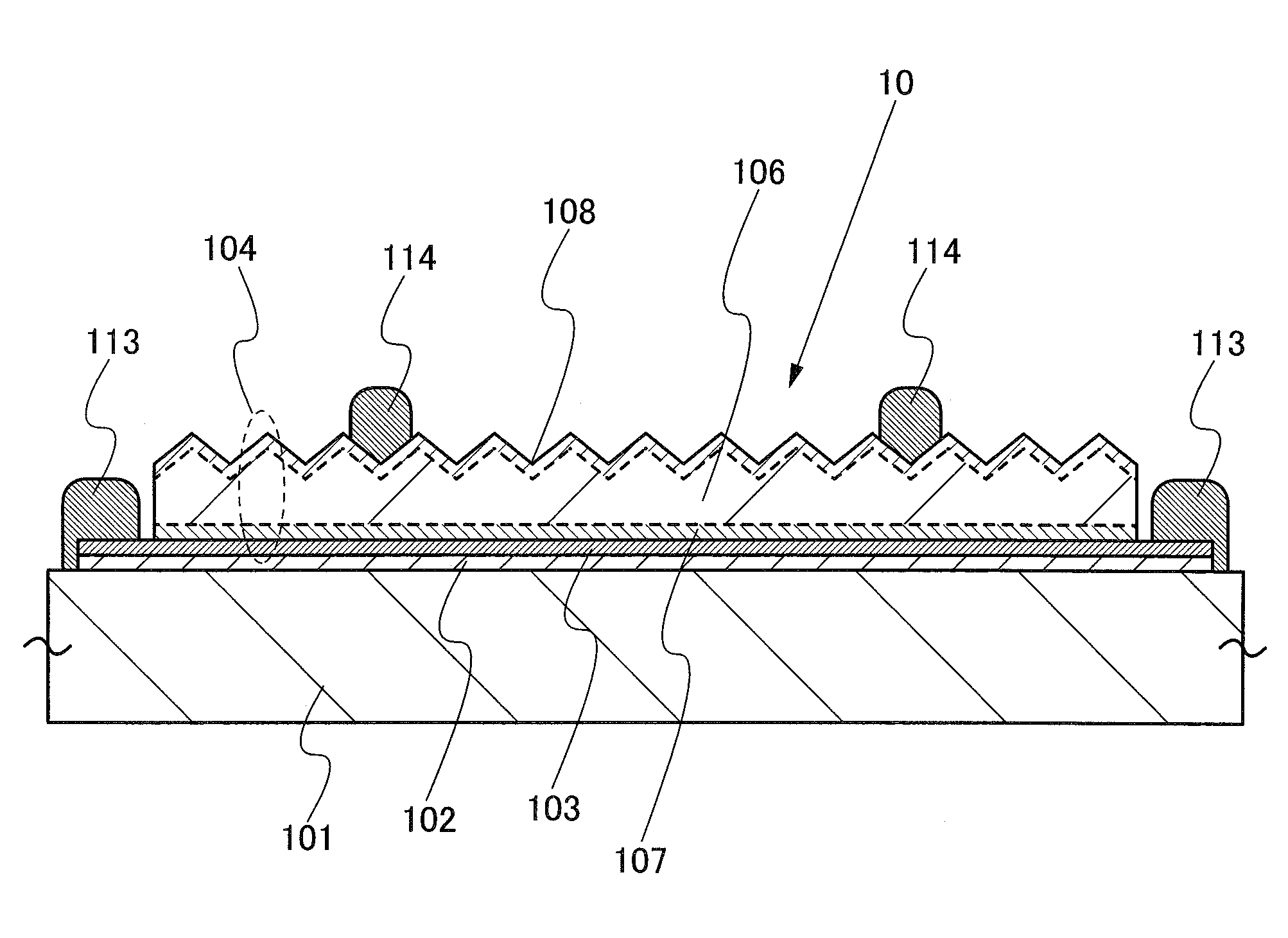
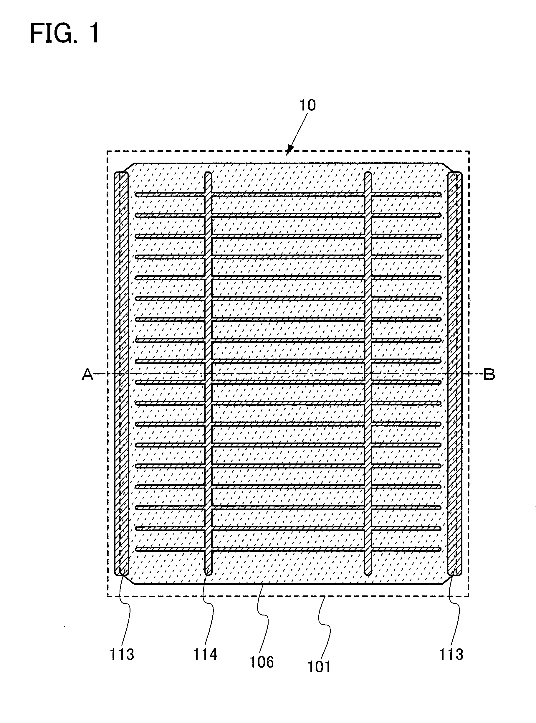
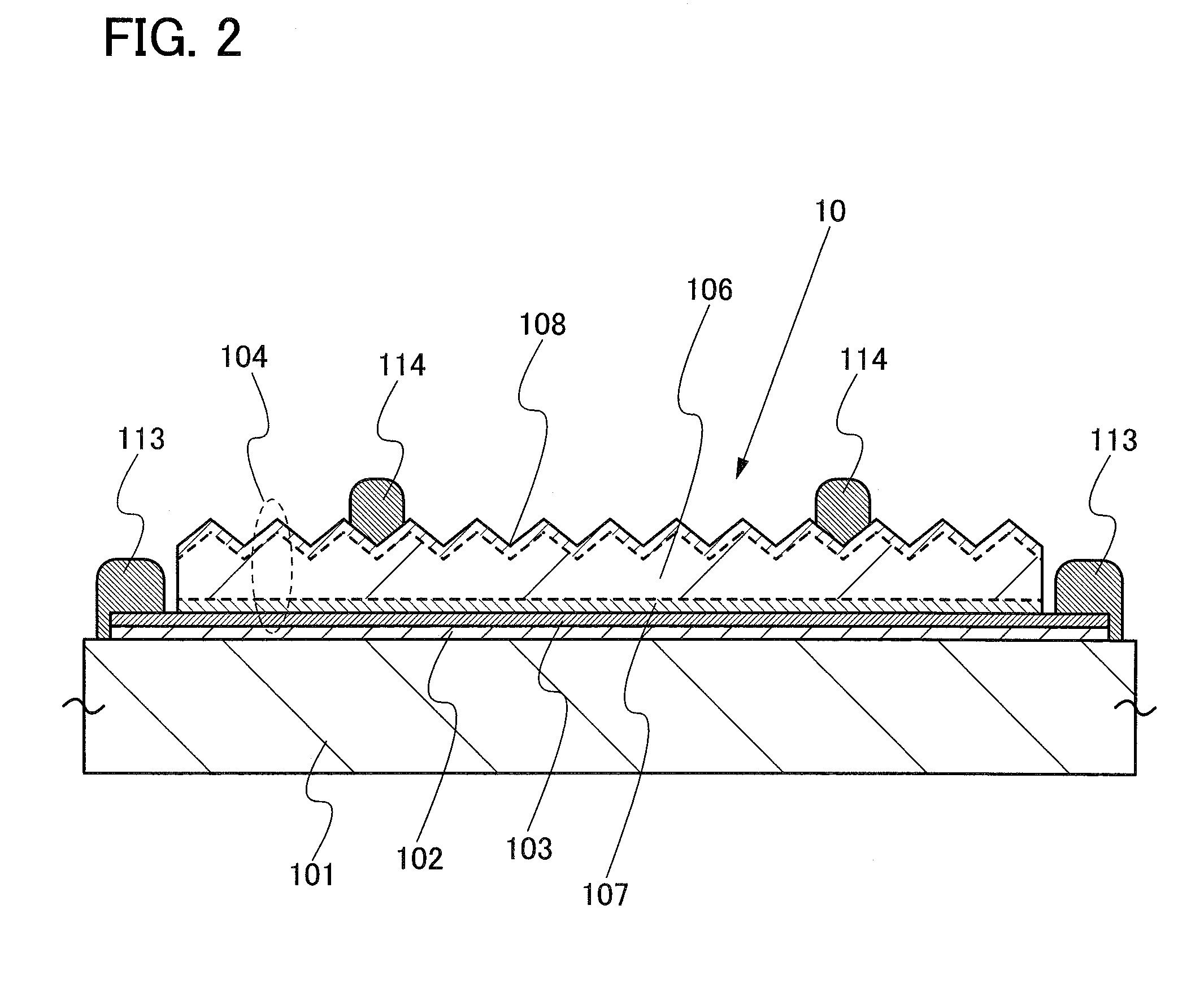
[0036]Described using drawings will be a method for manufacturing a photoelectric conversion device, in which a single crystal semiconductor thin layer is separated from a single crystal semiconductor substrate and transferred to a substrate having an insulating surface or an insulating supporting substrate.
[0037]FIG. 1 is a plan view of a photoelectric conversion device 10 of this embodiment mode. This photoelectric conversion device 10 produces a photoelectric effect by light incidence into a single crystal semiconductor layer 106 fixed on a supporting substrate 101. The single crystal semiconductor layer 106 is provided with an impurity semiconductor layer for forming an internal electrical-field. As the single crystal semiconductor layer 106, single crystal silicon is typically used. Alternatively, a polycrystalline semiconductor layer can be used instead of the single crystal semiconductor layer 106; in this case, polycrystalline silicon is used.
[0038]In FIG. 1, the surface sid...
embodiment mode 2
[0054]Next, a method for manufacturing the photoelectric conversion device 10 with its cross-sectional structure along section line A-B of FIG. 1 corresponding to the structure shown in FIG. 2 described in Embodiment Mode 1 will be described.
[0055]A semiconductor substrate 115 shown in FIG. 5A is a substrate with a shape approximately a quadrangular shape, cut out from a circular single crystal semiconductor substrate. The semiconductor substrate 115 is typically single crystal silicon and preferably has its surface polished to have a mirror surface. It is preferable that a protection film 116 be formed of silicon oxide or silicon nitride and a chemical vapor deposition method is used for the formation.
[0056]The first impurity semiconductor layer 107 having one conductivity type is formed in the semiconductor substrate 115. For example, boron is added as an impurity element which imparts one conductivity type so that the first impurity semiconductor layer 107 is formed to have p-typ...
embodiment mode 3
[0091]In this embodiment mode, manufacturing steps which are different from those in Embodiment Mode 2 will be described with reference to FIGS. 11A to 11C. The protection film 116 is formed and the first impurity semiconductor layer 107 is formed in the semiconductor substrate 115 (FIG. 11A), and then the damaged layer 117 is formed with the protection film 116 left (FIG. 11B). After that, the protection film 116 is removed and the first electrode 103 is formed (FIG. 11C). The process of this embodiment mode make it possible to effectively use the protection film 116. That is, the protection film 116 is removed after the formation of the damaged layer 117, so that a bonding surface of the semiconductor substrate 115 can be flat. It is preferable that the protection film 116 be provided to have a thickness of 50 to 200 nm. In addition, the damaged layer 117 is formed by introducing cluster ions of hydrogen through the first impurity semiconductor layer 107, so that hydrogenation of ...
PUM
 Abstract
Description
Claims
Application Information
 - R&D
- Intellectual Property
- Life Sciences
- Materials
- Tech Scout
- Unparalleled Data Quality
- Higher Quality Content
- 60% Fewer Hallucinations
Browse by: Latest US Patents, China's latest patents, Technical Efficacy Thesaurus, Application Domain, Technology Topic, Popular Technical Reports.
© 2025 PatSnap. All rights reserved.Legal|Privacy policy|Modern Slavery Act Transparency Statement|Sitemap|About US| Contact US: help@patsnap.com


