
Cutting tool and cutting device that have disk-like cutting blade

a cutting blade and cutting device technology, applied in the direction of metal sawing devices, manufacturing tools, metal sawing apparatus, etc., can solve the problems of cutting blade wear, deflective vibration, cutting blade wear, etc., and achieve high productivity, high accuracy, and high accuracy

Inactive Publication Date: 2009-05-07
OHNISHI KAZUMASA
View PDF5 Cites 8 Cited by
  • Summary
  • Abstract
  • Description
  • Claims
  • Application Information

AI Technical Summary

Benefits of technology

[0010]It is an object of the present invention to provide a cutting tool which can cut or groove an article under processing with a high accuracy regardless of thickness of the cutting blade.
[0011]It is another object of the invention to provide a cutting tool which is favorably employable for cutting an article with high accuracy and high yield or grooving an article with high accuracy and fine pitch.
[0026]The cutting blade of the cutting tool according to the invention is advantageous in that even a thin blade is used, the blade hardly vibrates in the thickness direction, because the blade is reinforced by a pair of the rigid plates arranged on both faces of the blade. Therefore, the cutting tool according to the invention can cut or groove an article with high accuracy, regardless of the thickness of the blade. Moreover, if a thin cutting blade is employed in the cutting tool of the invention, an article can be cut with high accuracy and high productivity or grooved with high accuracy and fine pitch.

Problems solved by technology

However, there are the following problems in the known cutting tool: when the cutting blade is very thin (thickness of 1 mm or less, particularly thickness 100 μm or less ), the cutting blade under application of ultrasonic oscillation is apt to vibrate not only in the radial direction but also in the thickness direction, that is, deflective vibration occurs, since the thin cutting blade is apt to deflect in the thickness direction.
Moreover, wear of the edge of the cutting blade increases.

Method used


Image

  • Cutting tool and cutting device that have disk-like cutting blade
  • Cutting tool and cutting device that have disk-like cutting blade
  • Cutting tool and cutting device that have disk-like cutting blade

Examples


Embodiment Construction

[0036]The cutting tool of the invention is described first, referring to the attached drawings.

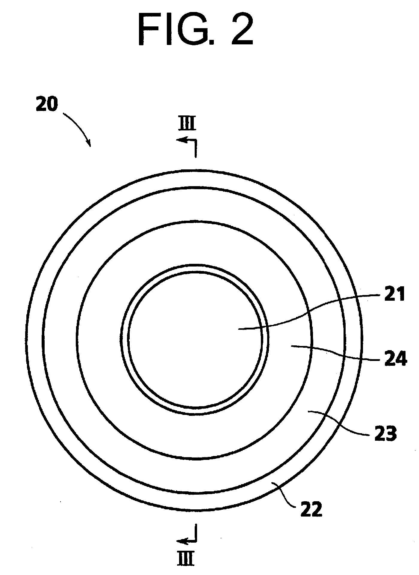
[0037]FIG. 2 is a front view illustrating one embodiment of the cutting tool according to the invention. FIG. 3 is a side section of the cutting tool taken along the line III-III shown in FIG. 2.

[0038]In FIGS. 2 and 3, the cutting tool 20 is composed of a cutting disk blade 22 having a through-hole 21 at its center, an annular rigid plate 23 coaxially fixed to each face of the cutting blade 22, and an annular ultrasonic oscillator 24 having a smaller outer diameter than the rigid plate 23 which is coaxially fixed to an outer face of each rigid plate 23.

[0039]The cutting disk blade 22 can be a known cutting blade such as a circular saw or a cutting disk blade composed of a disk substrate and abrasive grains fixed onto the surfaces of the disk substrate.

[0040]The disk substrate for the cutting blade can be made of metallic material such as aluminum, iron, or stainless steel.

[0041]The abrasiv...


PUM

PropertyMeasurementUnit
thicknessaaaaaaaaaa
thicknessaaaaaaaaaa
mean diameteraaaaaaaaaa

Abstract

A cutting tool (20) capable of cutting or grooving an article with high accuracy independent of the thickness of a cutting disk blade used has a cutting disk blade (22) having a through-hole (21) at its center, an annular rigid plate (23) coaxially fixed to each face of the cutting blade (22), and an annular ultrasonic oscillator (24) having a smaller outer diameter than the rigid plate (23) which is coaxially fixed to an outer face of each rigid plate (23) or to the cutting blade (22) in contact with an inner circumferential edge of each rigid plate (23).

Description

FIELD OF THE INVENTION[0001]This invention relates to a cutting tool having a cutting disk blade and a cutting machine which are favorably employable for cutting or grooving an article of rigid and fragile material such as inorganic glass, silicon, or silicon nitride.BACKGROUND OF THE INVENTION[0002]A cutting machine equipped with a cutting disk blade as a cutting tool is widely employed for cutting or grooving an article of rigid and fragile material such as inorganic glass, silicon, or silicon nitride. The cutting machine is operated to bring a circumferential edge of the disk blade under rotation into contact with the article to be processed.[0003]In the cutting procedure using the cutting machine for cutting a silicon wafer into a great number of silicon chips, it is required that the production yield (number of the silicon chips obtained by cutting one silicon wafer) is high. For this reason, the cutting machine is equipped with a thin disk blade which can produce a less amount...

Claims


Application Information

Patent Timeline
Patent Type & Authority Applications(United States)
IPC IPC(8): B28D1/04B26D7/08
CPCB28D1/24B23D47/12
Inventor OHNISHI, KAZUMASA
Owner OHNISHI KAZUMASA
Learn More