
Iron-base sintered part, manufacturing method of iron-base sintered part and actuator

a technology of iron-base sintered parts and manufacturing methods, applied in the direction of rotary piston liquid engine, solid-state diffusion coating, machines/engines, etc., to achieve the effect of increasing strength, toughness and abrasion resistan

Inactive Publication Date: 2009-05-07
JTEKT CORP
View PDF4 Cites 10 Cited by
  • Summary
  • Abstract
  • Description
  • Claims
  • Application Information

AI Technical Summary

Benefits of technology

[0009]Therefore, the present invention has been made in view of the above-mentioned problems, and it is an object of the present invention to provide an iron-base sintered part which has high precision and totally enhanced strength, toughness and abrasion resistance and is effective for higher performance and longer lifespan, a manufacturing method of the iron-base sintered part, and an actuator.
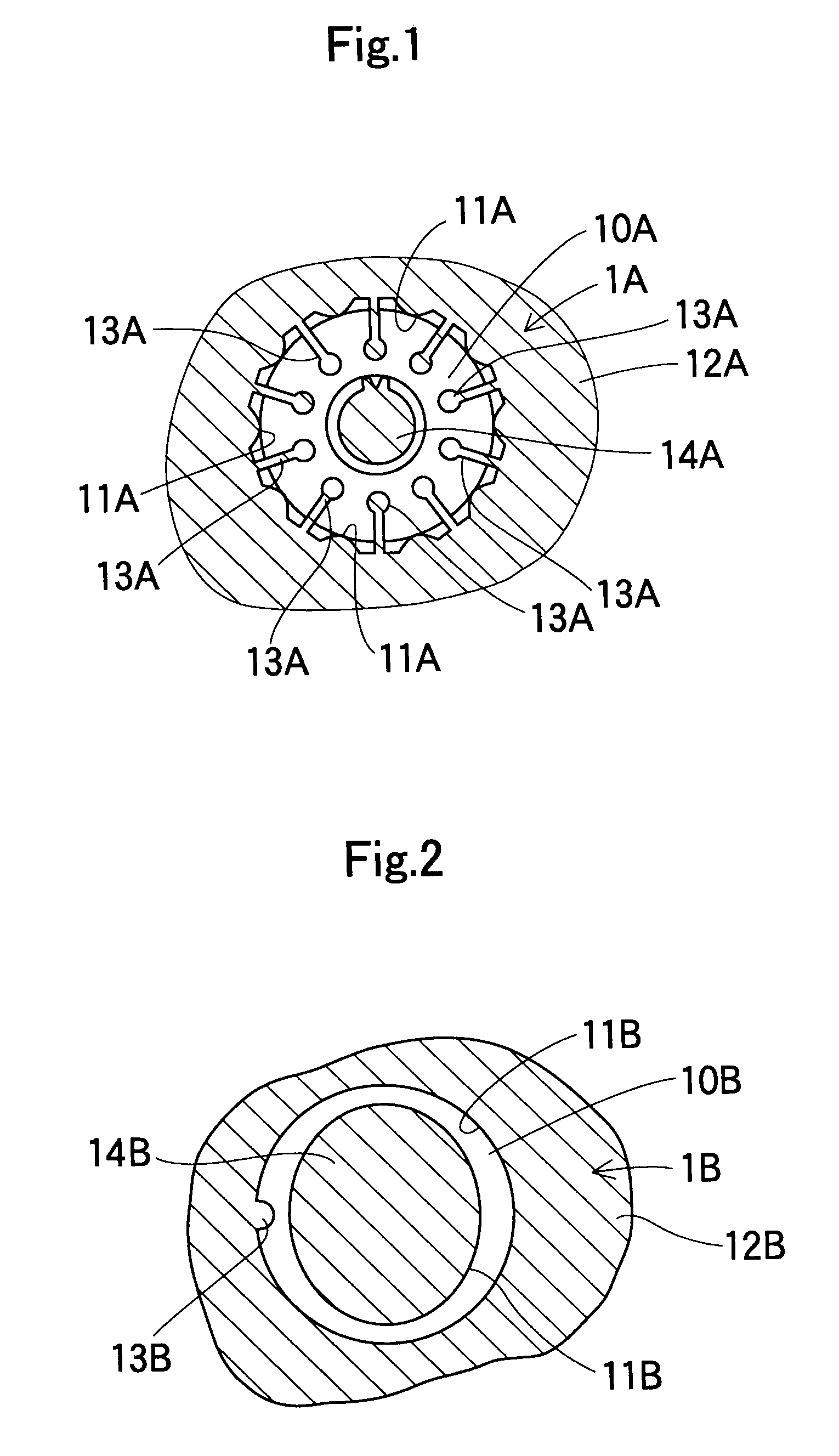
[0011]According to a second aspect of the present invention, a method for manufacturing the iron-base sintered part includes a molding process of charging a raw mixture powder of an iron-nickel-molybdenum-based metal powder and a carbon-based powder into a cavity of a molding die and compressing the raw powder in the cavity to form a consolidation body, a sintering process of sintering the consolidation body at a sintering temperature to form a sintered alloy, and a carburization quenching process of heating the sintered alloy in a carburization atmosphere and quenching the heated alloy. Thereby, the iron-base sintered part according to the aforementioned first aspect is formed. Accordingly, the iron-base sintered part having high density can be obtained.
[0013]Since the iron-base sintered part according to the present invention has a highly dense structure, in which density is set to 7.25 g / cm3 or more, strength, toughness and abrasion resistance can be totally increased.

Problems solved by technology

Further, in the process of generating the martensite-bainite mixed composition, residual austenite, which is effective for securing toughness, is not generated.

Method used


Image

  • Iron-base sintered part, manufacturing method of iron-base sintered part and actuator
  • Iron-base sintered part, manufacturing method of iron-base sintered part and actuator
  • Iron-base sintered part, manufacturing method of iron-base sintered part and actuator

Examples


first embodiment

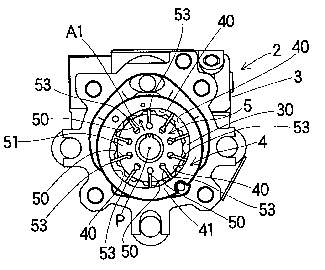
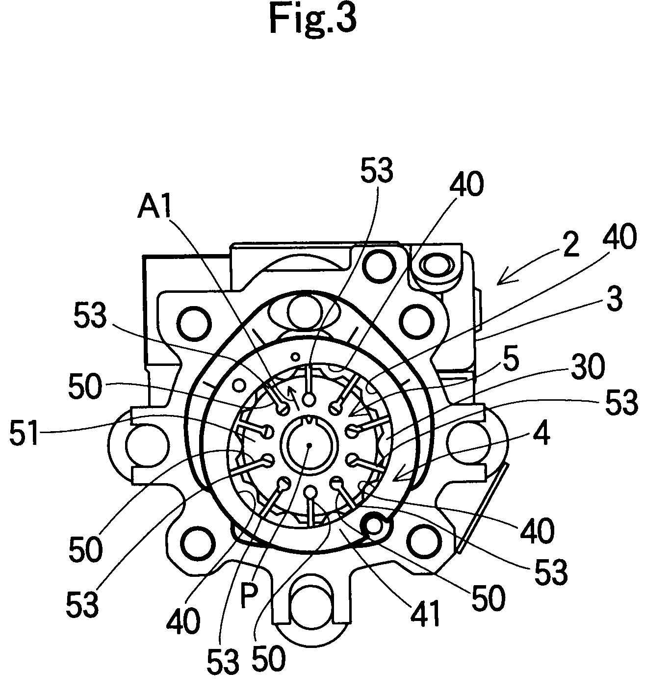
[0042]Hereinafter, the first embodiment of the present invention will be explained in detail with reference to the drawings. First, a method for manufacturing the rotor will be explained. As a metal powder for forming the rotor, an iron-base metal powder, which contains nickel of 4%, molybdenum of 0.50% and copper of 1.50%, with regard to a mass %, was prepared. Because carbon is not substantially included in the above metal powder, the hardness of the powder particle becomes low, and molybdenum is reduced and nickel is increased so as to enhance fatigue resistance of the sintered part. As such, in the metal powder for forming the rotor, as the element requiring the fatigue resistance, a ratio of the nickel quantity to the molybdenum quantity is set to be 8 (nickel quantity / molybdenum quantity=4.0% / 0.50%=8). Accordingly, the amount of residual austenite suitable for the rotor of the element requiring the abrasion resistance can be secured, while martensite is generated. The raw mixt...

second embodiment

[0060]A second embodiment has basically the same constitution and operational effects as the first embodiment. FIGS. 1 to 3 can be applied correspondingly to the second embodiment. According to this embodiment, both the rotor 51 and the cam ring 41 have density of 7.25 g / cm3 or more. Accordingly, the rotor 51 and the cam ring 41 are highly densified and have a very dense structure, and strength, abrasion resistance and fatigue strength are totally secured. Also while the rotor 51 and the cam ring 41 are highly densified, the rotor 51 and the cam ring 41 have a relation such that the density of the rotor 51 is larger than the density of the cam ring 41 (density of the rotor 51>density of the cam ring 41). Thus, since the carburizer easily penetrates into the cam ring 41 in the carburization process, strength and fatigue strength of the cam ring 41 can be secured, and further the carburizing amount in the vicinity of the cam surface 40, which is the surface of the cam ring 41, can be ...

third embodiment

[0061]A test example will be explained. A test specimen (size: 55 mm×10 mm×5 mm, basic composition: Ni: 4%, Cu: 1.50%, Mo: 0.50%, remainder: Fe) having a composition corresponding to the rotor 51 according to the aforementioned embodiment was manufactured, and a test was carried out with respect to a relation of transverse strength, fatigue strength (stress level at which failure does not occur even after the stress of a predetermined magnitude is applied for ten million cycles or more) and density. FIG. 4 shows a relation of the density (g / cm3) and the transverse strength (relative value) of the test specimen. FIG. 5 shows a relation of the density (g / cm3) and the fatigue limit (relative value) of the test specimen. As shown by a characteristic line W1 in FIG. 4, the transverse strength shows the maximum value when the density is around 7.3. As shown by a characteristic line W2 in FIG. 5, the fatigue strength shows the maximum value when the density is around 7.4. As such, as the d...


PUM

PropertyMeasurementUnit
Temperatureaaaaaaaaaa
Fractionaaaaaaaaaa
Fractionaaaaaaaaaa

Abstract

An iron-base sintered part having high density and totally enhanced strength, toughness and abrasion resistance, a manufacturing method of the iron-base sintered part, and an actuator are disclosed. The iron-base sintered part is formed by an iron-nickel-molybdenum-carbon-based sintered alloy, has density of 7.25 g / cm3 or more, and has a carburization quenched structure. A method for manufacturing the iron-base sintered part includes a molding process of charging a raw mixture powder of an iron-nickel-molybdenum-based metal powder and a carbon-based powder into a cavity of a molding die and compressing the raw powder in the cavity to form a consolidation body, a sintering process of sintering the consolidation body at a sintering temperature to form a sintered alloy, and a carburization quenching process of heating the sintered alloy in a carburization atmosphere and quenching the heated alloy.

Description

BACKGROUND OF THE INVENTION[0001]1. Field of the Invention[0002]The present invention relates to an iron-base sintered part having an excellent strength, a manufacturing method of the iron-base sintered part and an actuator.[0003]2. Description of the Related Art[0004]Patent Reference 1 discloses a manufacturing method of a sintered part, in which carbon of 0.6 to 0.9 wt % is added in a composite alloy iron base powder, including Ni, Cu, Mo, etc., the powder combined with zinc stearate as a forming lubricant is put into a molding die, a forming body having density of 7.0 to 7.2 g / cm3 is formed, the forming body is sintered at a temperature of 1250 to 1300° C. and then is cooled continuously, thereby generating a martensite-bainite mixed composition. Also, Patent Reference 2 discloses Fe-base alloy having superior abrasion resistance, which is formed by impregnating a carbide precipitated type Fe-base sintered alloy having 5 to 20% porosity with Pb or Pb alloy.[0005][Patent Reference...

Claims


Application Information

Patent Timeline
IPC IPC(8): C23C8/66F16H25/00
CPCB22F3/1007Y10T74/18544B22F2003/026B22F2998/00B22F2998/10C22C33/0264C22C38/08C22C38/12C22C38/16F01C21/08F01C21/106F04C2/3446F04C2230/22F05C2201/0409F05C2201/046F05C2201/0466B22F2003/023B22F5/08B22F3/24B22F2201/30B22F3/02B22F3/1028
Inventor SAITO, TOSHIYUKIMIO, TAKUMINISHI, KOJIFUKAMI, HAJIMEYAMAUCHI, KENTAROYAO, HIROYUKIYAMAMOTO, MASAYUKIYAMAZAKI, HIDEKI
Owner JTEKT CORP
Learn More