
Plasma display panel and manufacturing method of the same

a plasma display and manufacturing method technology, applied in the manufacture of electric discharge tubes/lamps, gas discharge sealing, electromechanical systems, etc., can solve the problems of reducing the manufacturing efficiency of pdp, increasing the initial cost and running cost of the manufacturing apparatus, and significantly inferior metal hydroxide compounds in sputter resistance and secondary electron emission coefficient. , to achieve the effect of reducing power consumption and low viscosity

Inactive Publication Date: 2009-04-23
HITACHI LTD
View PDF3 Cites 1 Cited by
  • Summary
  • Abstract
  • Description
  • Claims
  • Application Information

AI Technical Summary

Benefits of technology

[0011]Incidentally, the metal oxide used for the protective layer of the PDP has a property of easily adsorbing moisture in the air. If the moisture is adsorbed in the metal oxide, the metal oxide reacts with water to be deliquesced or transformed to a metal hydroxide compound. This metal hydroxide compound is significantly inferior to metal oxides in sputter resistance and secondary electron emission coefficient. Therefore, the crystal structure of the protective layer tends to be destroyed by sputter. Also, it becomes disadvantageously impossible to reduce a firing voltage.
[0015]The present invention has been made in consideration of the problems mentioned above, and an object of the present invention is to provide a technology capable of improving a manufacturing efficiency of the PDP.
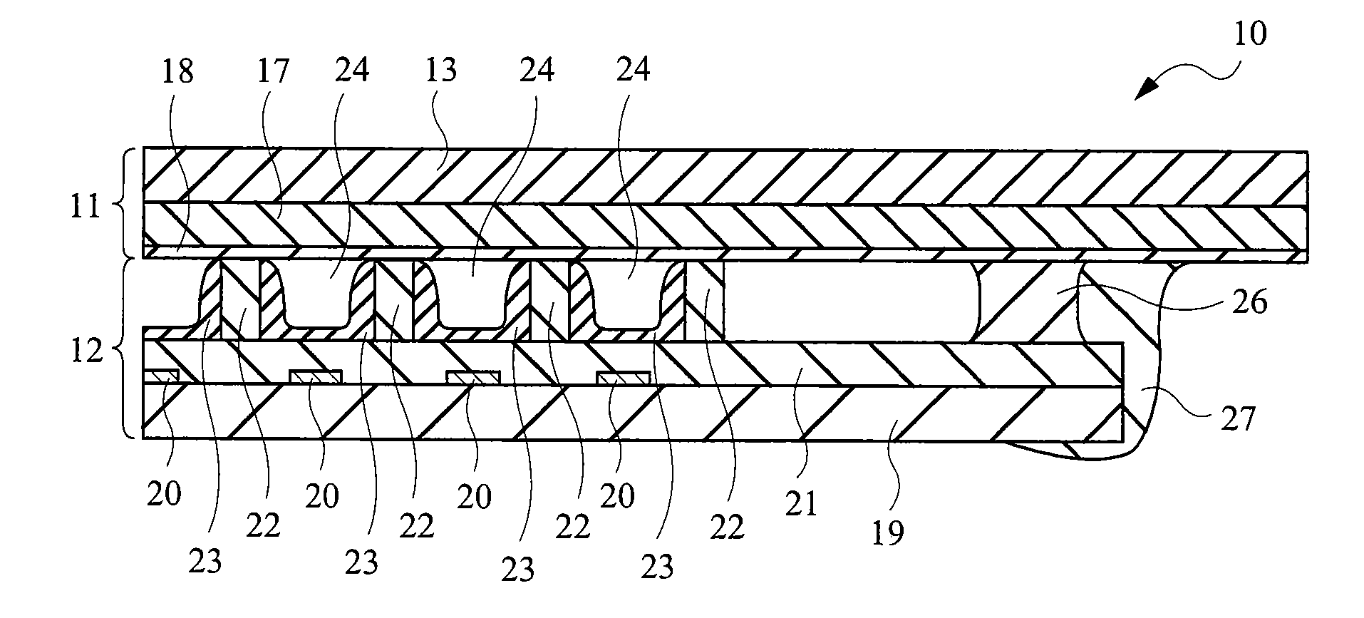
[0017]More specifically, the present invention provides a plasma display panel comprising a first structure and a second structure disposed so as to be opposed to each other, wherein the first structure and the second structure are sealed with a sealing material which is disposed so as to surround a plurality of barrier ribs formed on one surface of the second structure and has a gas barrier characteristic, and the first structure and the second structure are fixed with an adhesive agent which is disposed on an outer side of the sealing material with respect to the barrier ribs and has lower viscosity than the sealing material.

Problems solved by technology

Accordingly, there arises a problem that a manufacturing efficiency of the PDP is lowered.
Accordingly, there arises a problem that an initial cost and a running cost of the manufacturing apparatus are increased.
This metal hydroxide compound is significantly inferior to metal oxides in sputter resistance and secondary electron emission coefficient.
Therefore, the crystal structure of the protective layer tends to be destroyed by sputter.
Also, it becomes disadvantageously impossible to reduce a firing voltage.

Method used


Image

  • Plasma display panel and manufacturing method of the same
  • Plasma display panel and manufacturing method of the same
  • Plasma display panel and manufacturing method of the same

Examples


first embodiment

[0033]

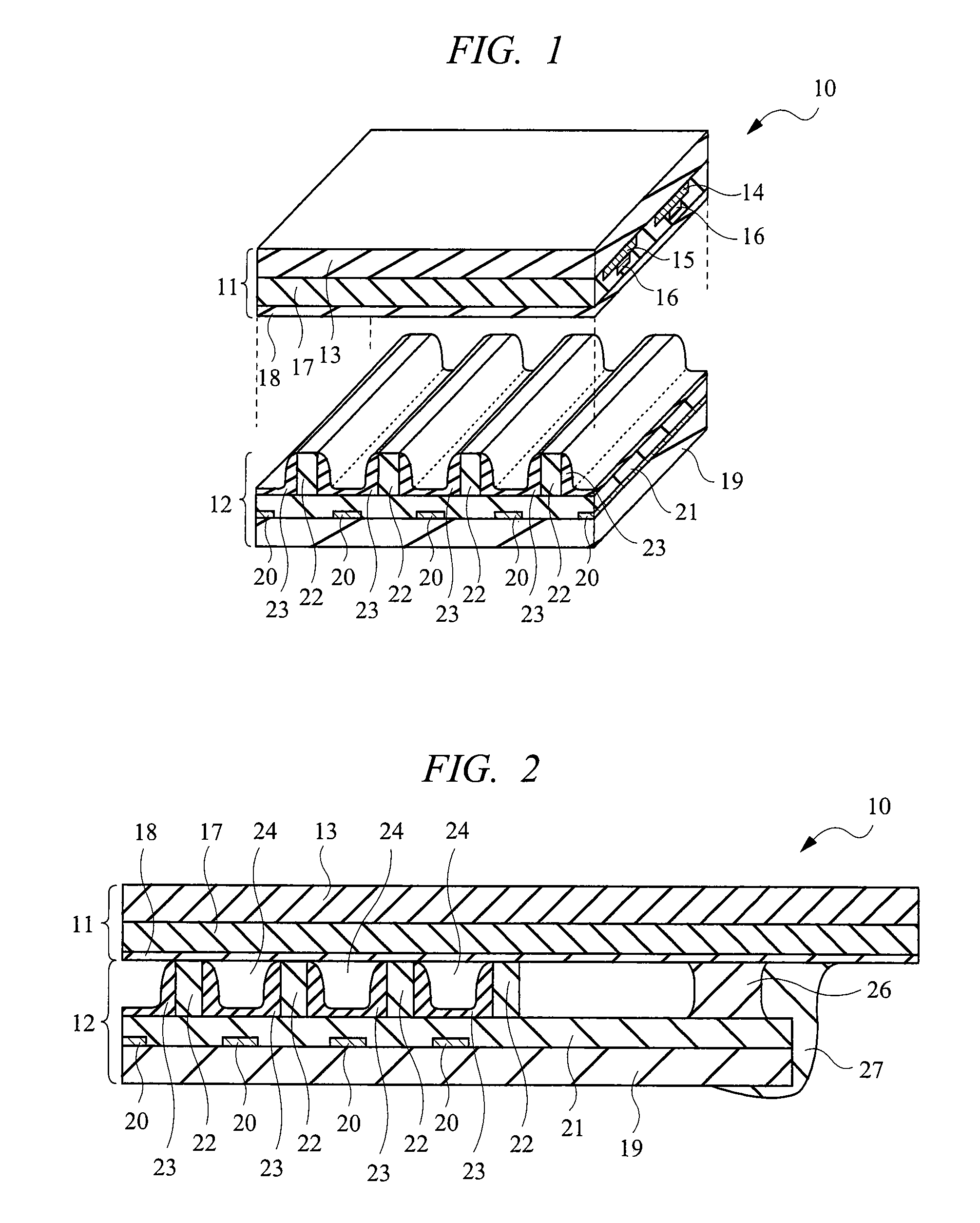
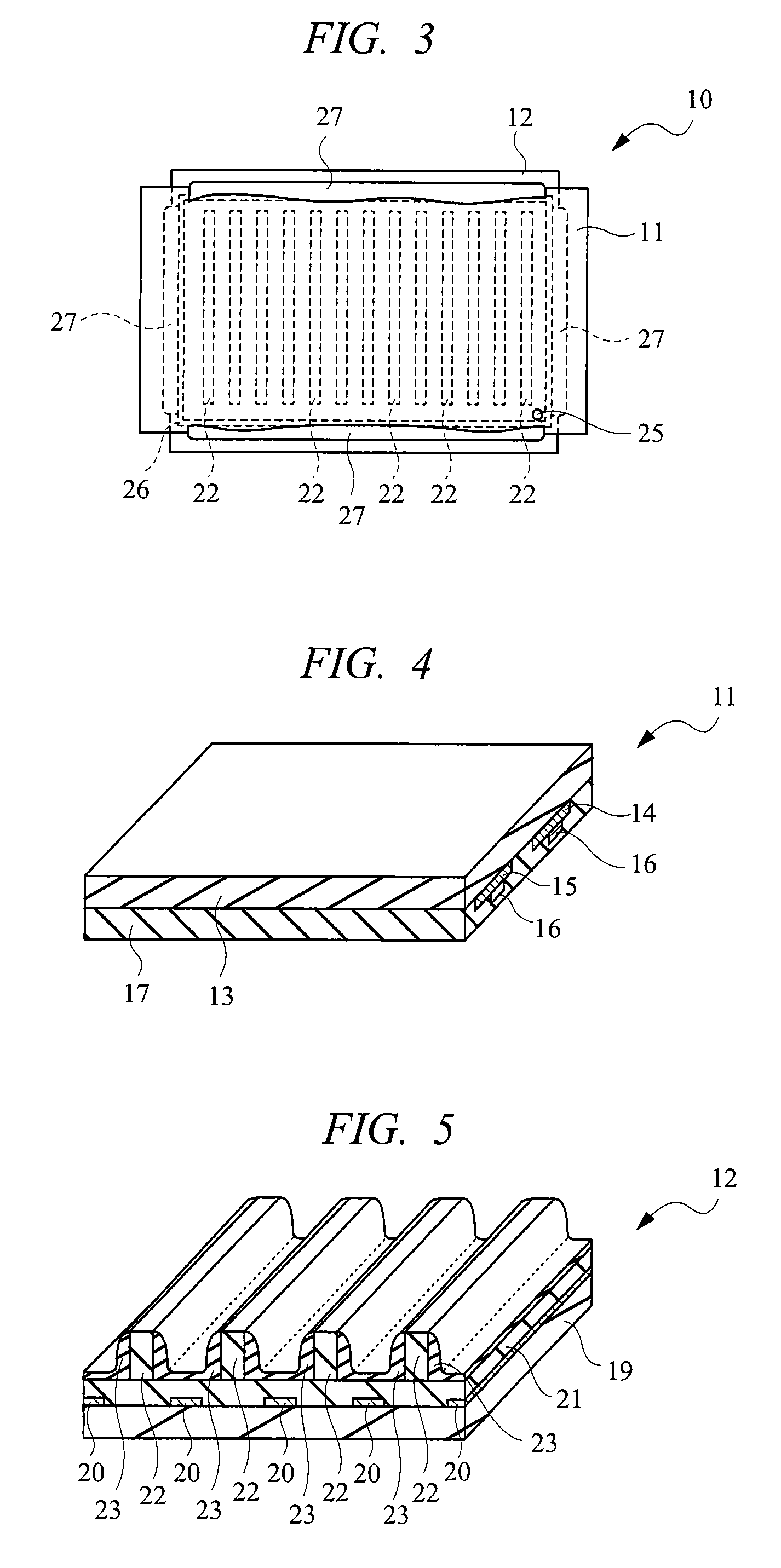
[0034]First, the structure of a PDP according to a first embodiment will be described with reference to FIGS. 1 to 3, in which an alternating-current surface discharge type PDP is used as an example. FIG. 1 is an enlarged perspective view showing the principal part of the PDP according to the first embodiment in an enlarged manner, FIG. 2 is an enlarged cross sectional view showing the principal part of the structure of an end portion of a front structure and a rear structure in a state where the front structure and the rear structure shown in FIG. 1 are laminated, and FIG. 3 is a plan view showing the front structure of the PDP in which the front structure and the rear structure are laminated in a transparent manner. Note that, for easy description of the structure of the PDP, FIG. 1 shows the state where the front structure and the rear structure are away from each other more than a predetermined space.

[0035]In FIG. 1, a PDP 10 has a front structure (first structure) 11 and ...

first modified embodiment

of the First Embodiment

[0109]As a first modified embodiment of the first embodiment, the structure as shown in FIG. 12 can be employed. FIG. 12 is an enlarged cross sectional view showing the principal part of a structure of a peripheral portion of a panel structure in which a front structure and a rear structure are combined, in a manufacturing method of a PDP according to the first modified embodiment of the first embodiment.

[0110]The difference between the PDP 30 shown in FIG. 12 and the PDP 10 shown in FIG. 7 lies in that a dummy barrier rib (second barrier rib) 31 is disposed between the vacuum grease 26 and the barrier rib (first barrier rib) 22 disposed on an outermost side. As shown in FIG. 12, by forming the dummy barrier rib 31 between the vacuum grease 26 and the barrier rib 22 disposed on the outermost side, it becomes possible to prevent the vacuum grease 26 from entering an inner space of the PDP 30. Further, it is also possible to adjust an interval between the front ...

second modified embodiment

of the First Embodiment

[0111]As a second modified embodiment of the first embodiment, the following manufacturing method can be employed.

[0112]More specifically, although the sealing step (c1) has been described as the step performed under the vacuum (reduced pressure) atmosphere, the atmosphere of the PDP 10 shown in FIG. 2 is replaced with the discharge gas conditioned at a predetermined pressure. The discharge gas introducing step (c4) and the sealing step (c5) can be omitted by performing the sealing step under the discharge gas atmosphere conditioned at the predetermined pressure.

[0113]Therefore, the number of manufacturing steps can be reduced, and the manufacturing efficiency of the PDP 10 can be further improved.

[0114]Incidentally, since it is inevitable that the manufacturing apparatus has a complicated mechanism when the sealing step (c1) is performed after the alignment step (c2), it is necessary to secure an operating space of the complicated mechanism. Therefore, the ca...


PUM


Abstract

The present invention improves a manufacturing efficiency of a plasma display panel. In a plasma display panel (PDP) having a front structure (first structure) and a rear structure (second structure) which are disposed so as to be opposed to each other, the front structure and the rear structure are sealed with vacuum grease (sealing material) which is disposed so as to surround a plurality of barrier ribs formed on one surface of the rear structure and has a gas barrier characteristic, and they are fixed to each other with an adhesive agent which is disposed on an outer side of the vacuum grease with respect to the barrier ribs and has a lower viscosity than the vacuum grease.

Description

CROSS-REFERENCE TO RELATED APPLICATION[0001]The present application claims priority from Japanese Patent Application No. JP 2007-271021 filed on Oct. 18, 2007, the content of which is hereby incorporated by reference into this application.TECHNICAL FIELD OF THE INVENTION[0002]The present invention relates to a technology for a plasma display. More particularly, it relates to a technology effectively applied to a plasma display panel in which a peripheral portion of a pair of substrates is sealed in a state where these substrates are opposed to each other.BACKGROUND OF THE INVENTION[0003]A plasma display panel (PDP) is a display panel in which a gas discharge is generated in a discharge space called a cell filled with a discharge gas such as a rare gas and phosphors are excited by vacuum ultraviolet rays generated at the time of this discharge, thereby displaying an image.[0004]In general, the PDP has a structure in which a pair of substrates is laminated in a state of being opposed ...

Claims


Application Information

Patent Timeline
Patent Type & Authority Applications(United States)
IPC IPC(8): H01J9/26H01J17/49H01J11/24H01J11/46H01J11/48
CPCH01J9/261H01J11/48H01J11/12H01J11/34
Inventor WATABE, MASAHIRO
Owner HITACHI LTD
Learn More