
Dielectric spacer removal

a technology of dielectric spacers and dielectric plates, which is applied in the direction of semiconductor devices, electrical apparatus, transistors, etc., can solve the problems of limiting technology, lateral etch/undercut which is inherent in wet etch processes at the gate level cannot be tolerated at the pitch used in advanced technologies, and the etch rate is very low, so as to facilitate different applications of stress engineering, reduce the likelihood of electrical contact failure, and enhance mobility

Inactive Publication Date: 2009-03-12
GLOBALFOUNDRIES INC
View PDF3 Cites 11 Cited by
  • Summary
  • Abstract
  • Description
  • Claims
  • Application Information

AI Technical Summary

Benefits of technology

[0043]The present invention relates to semiconductor devices, and more particularly to a process and structure for removing dielectric spacers selective to a surface of a semiconductor substrate with substantially no removal of the semiconductor substrate. Depositing at least one sacrificial layer over the gate structure to remove the dielectric spacers without causing a substantial recess in the semiconductor substrate greatly reduces the likelihood of an electrical contact failure and facilitates different applications of stress engineering for enhanced mobility and integration of advanced gate structures.

Problems solved by technology

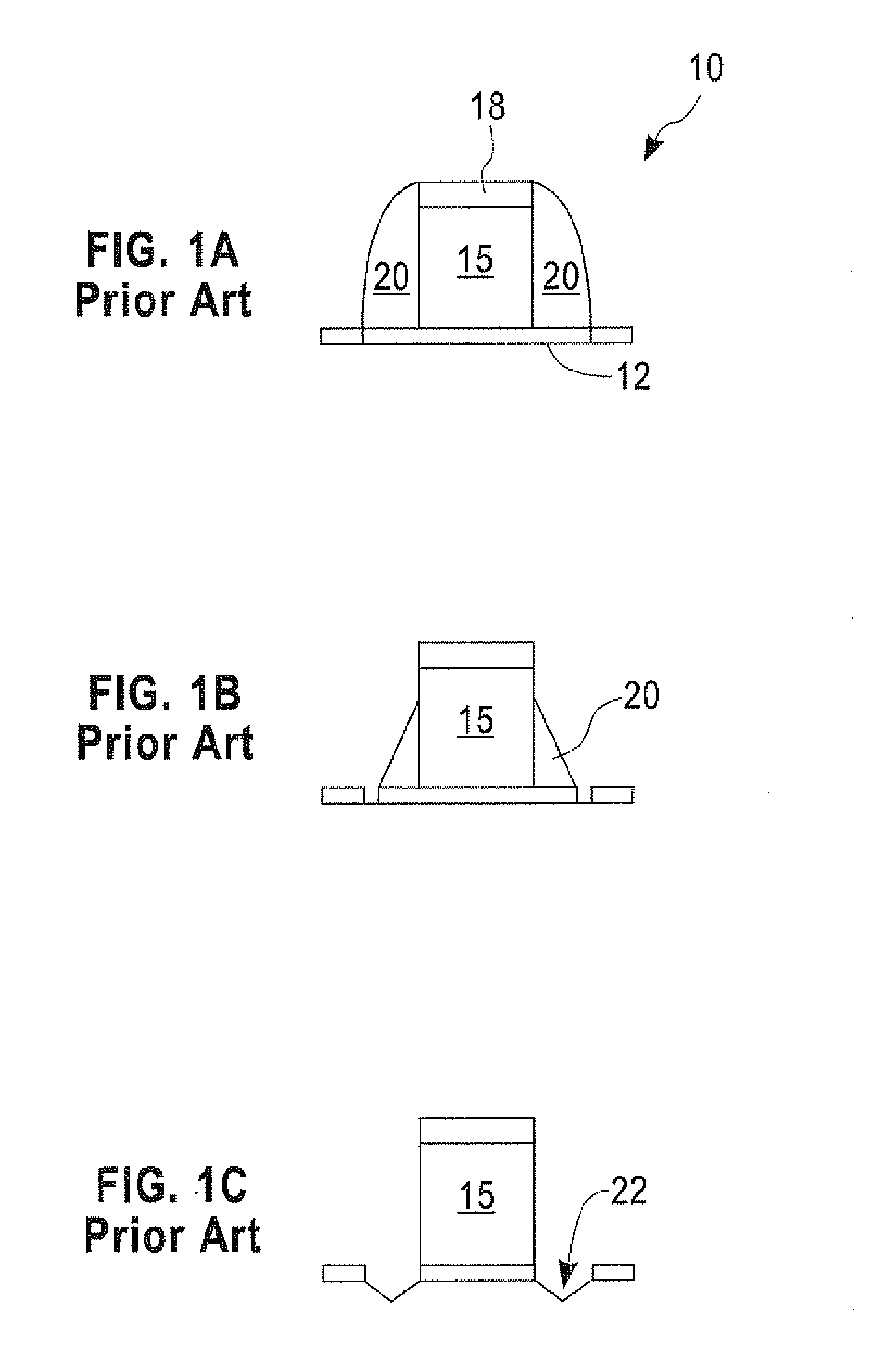
However, there are technology-limiting drawbacks with each methodology.
Specifically, lateral etch / undercut which is inherent to wet etch processes at the gate level cannot be tolerated at the pitch used in advanced technologies.
Furthermore, the wet etch rate is very low relative to RIE, leading to process times that are longer than desired.
RIE process times are relatively shorter than wet etch processes, but there are several problems with RIE-based methods.
First, it is difficult to etch the dielectric spacer selective to p-doped and more importantly, n-doped Si in the extension and S / D regions of the semiconductor device.
This lack of specificity can lead to severe negative device performance.
This leads to a loss of electrical contact between the gate and the S / D.
Furthermore, it is difficult to remove densified silicon nitride selective to metal silicide.
Damage to the silicide used to contact the gate and S / D can lead to higher contact resistance or even electrical shorts.
Additionally, it is difficult to remove densified silicon nitride selective to oxide.
This is especially problematic because oxide is often used as a composite spacer material and oxide is used for fill in shallow trench isolation.

Method used


Image

  • Dielectric spacer removal
  • Dielectric spacer removal
  • Dielectric spacer removal

Examples


Embodiment Construction

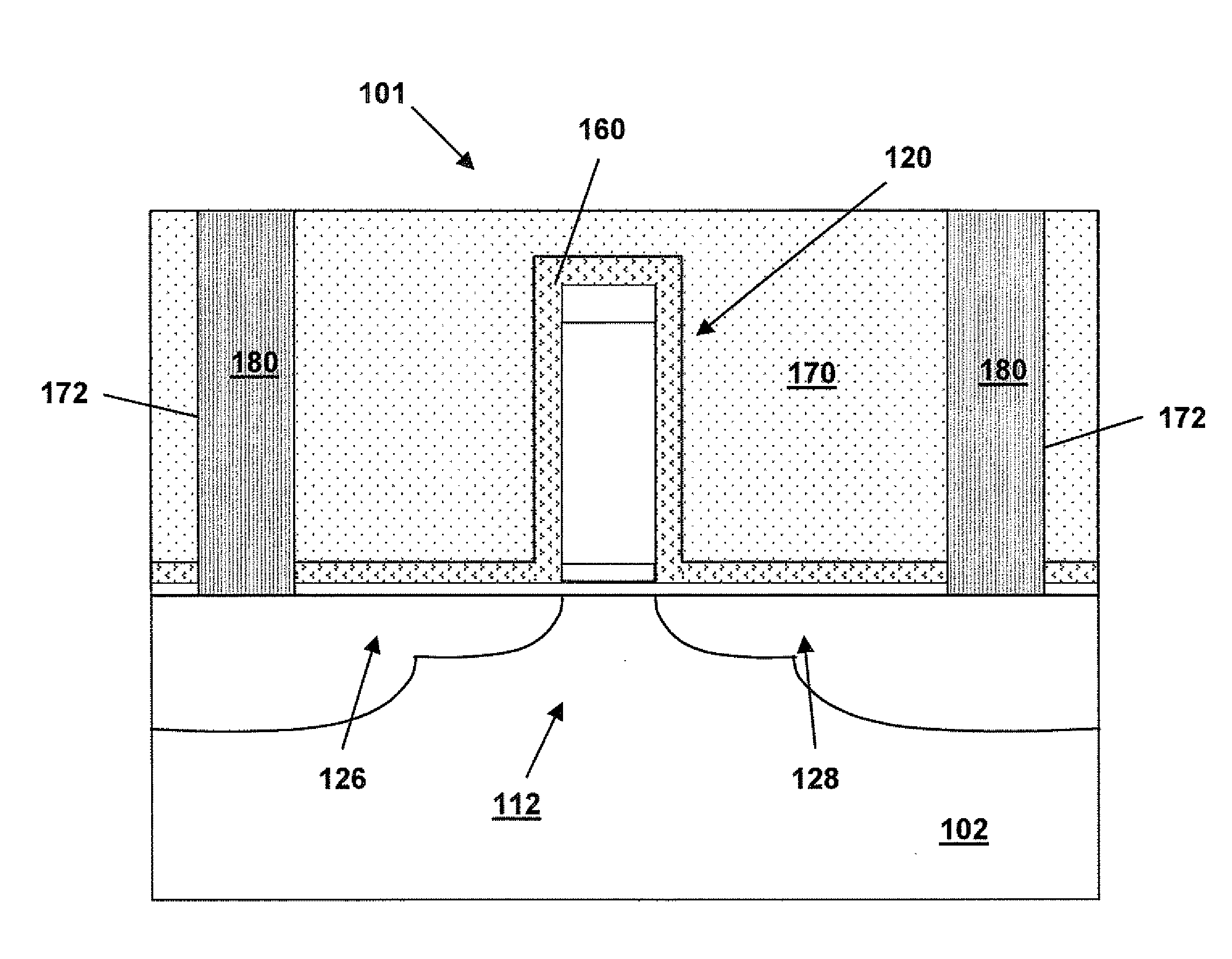
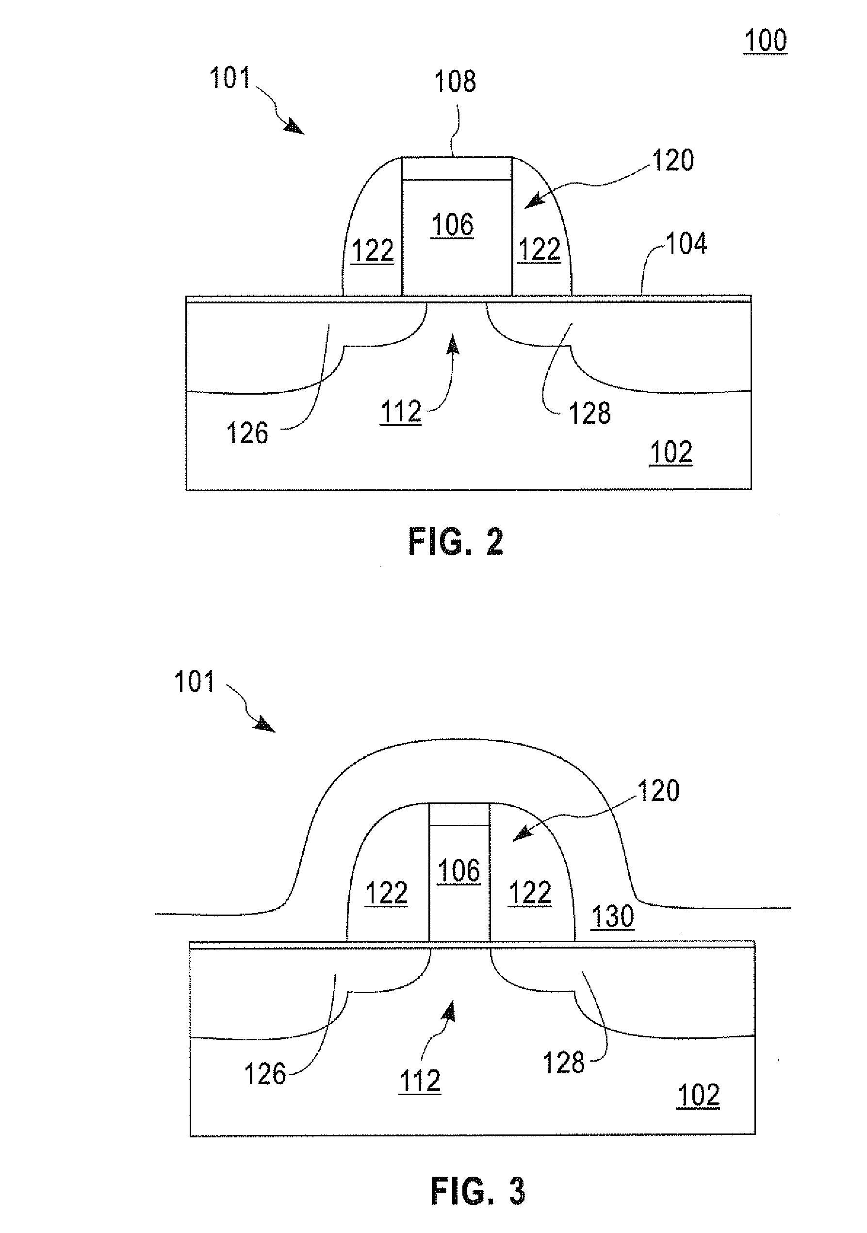
[0050]The present invention, which provides a semiconductor device comprising a semiconductor substrate having substantially no recesses in the semiconductor substrate after dielectric spacer removal, as well as a method of fabricating the same will now be described in greater detail by referring to the drawings that accompany the present application. It is noted that the drawings of the present application are provided for illustrative purposes and are thus not drawn to scale. Moreover, like and corresponding elements shown in the drawings are referred to by like reference numerals.

[0051]Reference is made to FIGS. 2-6, which are cross sectional views of a semiconductor structure during various stages of an embodiment of the present invention. Although the drawings show the presence of a single gate (i.e., a CMOS transistor structure with either pFET and / or nFET transistors), the present invention is not limited to that number of gates. Instead, the present integration process works...


PUM


Abstract

The present invention relates to semiconductor devices, and more particularly to a process and structure for removing a dielectric spacer selective to a surface of a semiconductor substrate with substantially no removal of the semiconductor substrate. The method of the present invention can be integrated into a conventional CMOS processing scheme or into a conventional BiCMOS processing scheme. The method includes forming a field effect transistor on a semiconductor substrate, the FET comprising a dielectric spacer and the gate structure, the dielectric spacer located adjacent a sidewall of the gate structure and over a source / drain region in the semiconductor substrate; depositing a first nitride layer over the FET; and removing the nitride layer and the dielectric spacer selective to the semiconductor substrate with substantially no removal of the semiconductor substrate.

Description

FIELD OF THE INVENTION[0001]The present invention relates to semiconductor devices, and more particularly to a process and structure for removing dielectric spacers selective to a surface of a semiconductor substrate with substantially no removal of the semiconductor substrate.BACKGROUND OF THE INVENTION[0002]Complementary metal-oxide semiconductors (CMOS) are a major class of integrated circuits (ICs). CMOS chips include microprocessors, microcontrollers, static random access memory (RAM), and other digital logic circuits. An advantage of CMOS technology is that it only uses significant power when its transistors are switching between on and off states. Consequently, CMOS devices use significantly less power and produce less heat than other forms of logic devices. CMOS technology also allows a high density of logic functions on a chip. “Metal-oxide-semiconductor” is a reference to the fabrication of early (and in some cases, the very latest) field-effect transistors, having a metal...

Claims


Application Information

Patent Timeline
IPC IPC(8): H01L21/311H01L29/78
CPCH01L21/31116H01L29/6653H01L29/7843H01L29/7833H01L29/6659
Inventor CARTIER, EDUARD A.JHA, RASHMIKANAKASABAPATHY, SIVANANDALI, XIMO, RENEE T.NARAYANAN, VIJAYPARUCHURI, VAMSIROBSON, MARK T.SCHONENBERG, KATHRYN T.STEEN, MICHELLE L.WISE, RICHARDZHANG, YING
Owner GLOBALFOUNDRIES INC
Learn More