
Engraving of printing plates

a printing plate and engraving technology, applied in the direction of printing, optical resonator shape and construction, manufacturing tools, etc., can solve the problems of high cost per watt ratio of laser, large amount of debris generated by engraving process of flexographic plate production, and adds extra complexity and cost to the process

Inactive Publication Date: 2009-03-05
MIRACLON CORP
View PDF5 Cites 27 Cited by
  • Summary
  • Abstract
  • Description
  • Claims
  • Application Information

AI Technical Summary

Benefits of technology

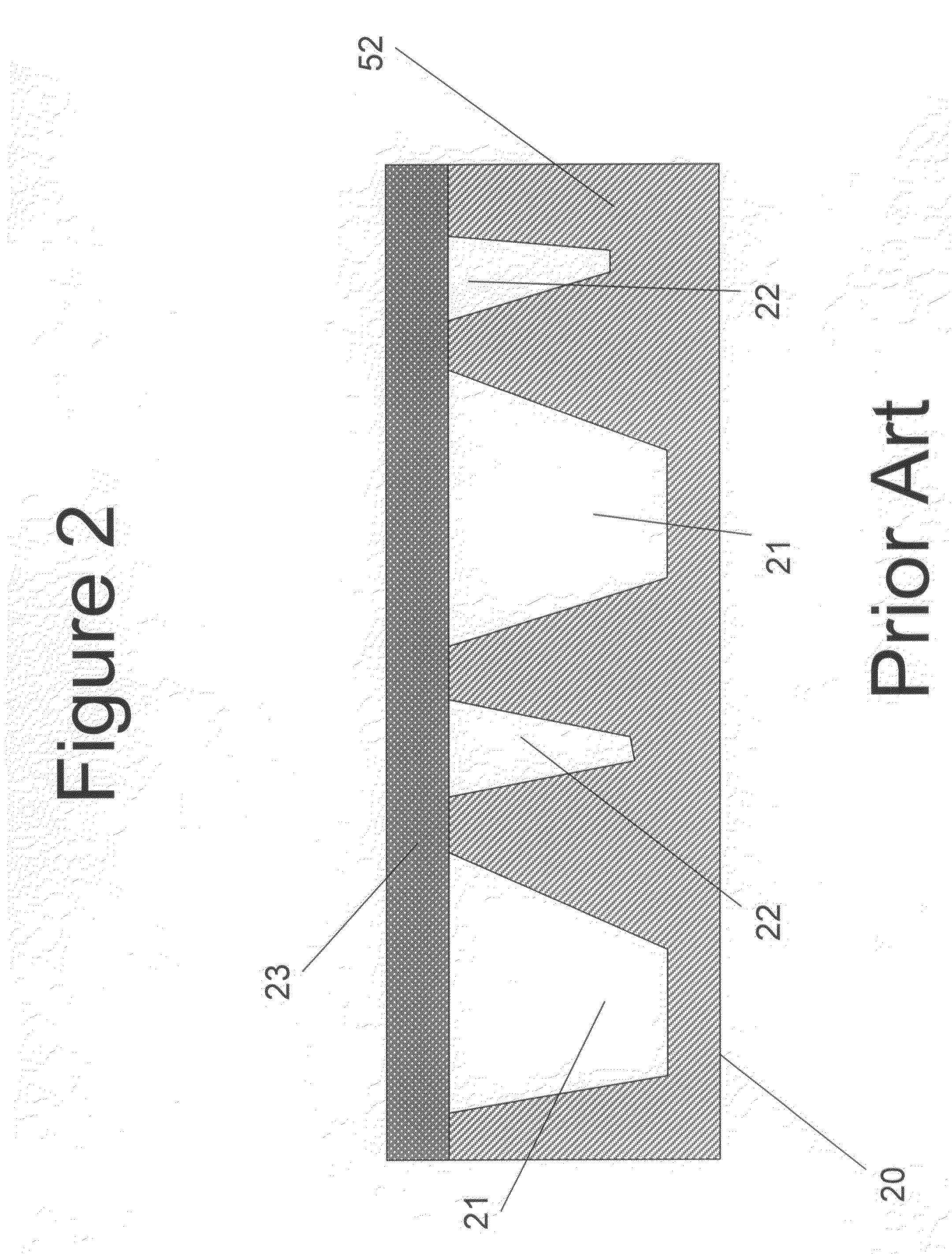
[0010]The engraving by slicing system (“EBS”) according to the present invention takes advantage of the fact that while large solid areas need to be processed by the laser to a certain depth relief, fine detail areas can be processed to significantly shallower relief.

Problems solved by technology

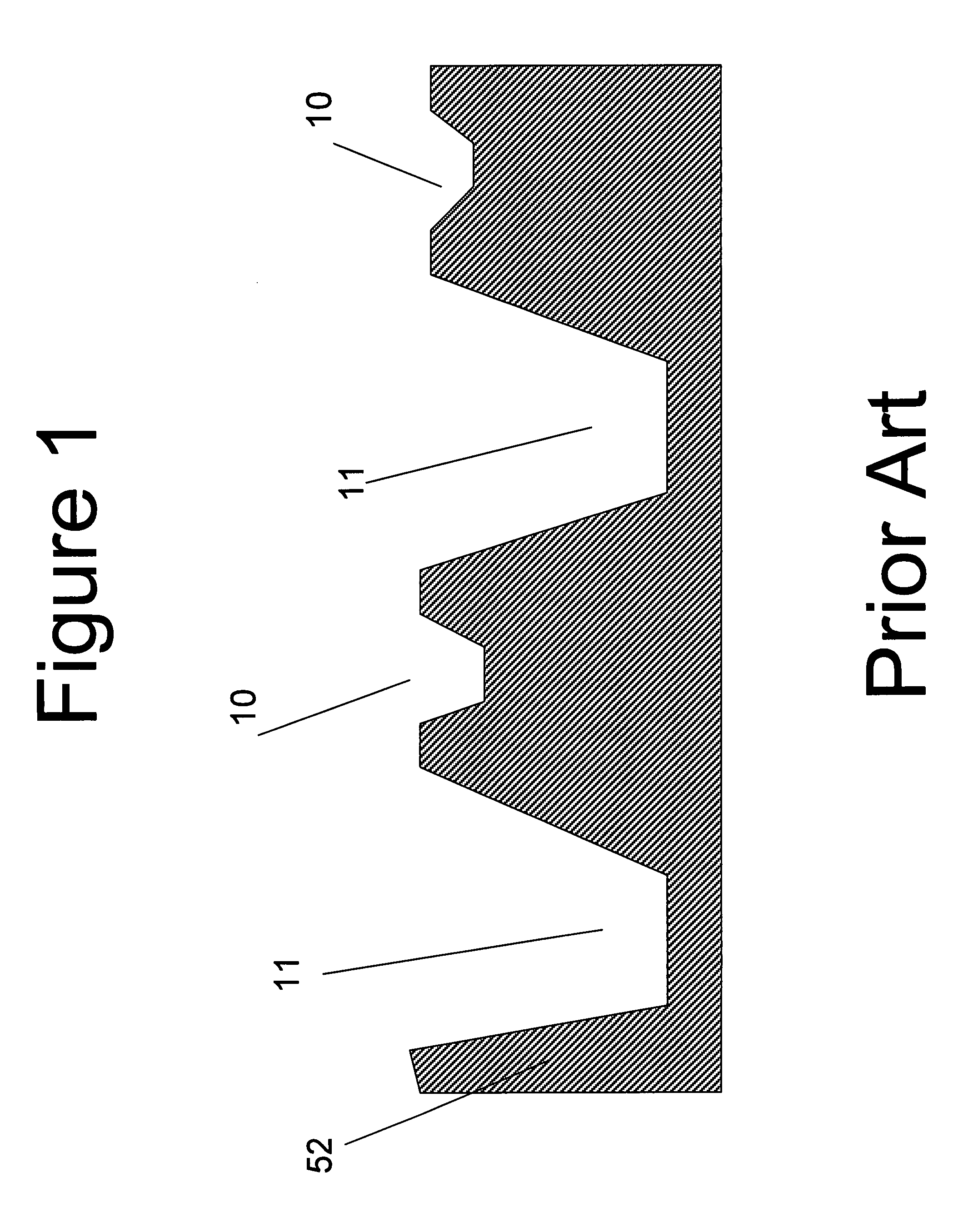
This difference introduces several challenges for a laser imaging system for flexographic plates: the laser system must have sufficient power to ablate the material, and the laser spot should be small enough to achieve the fine detail required in quality printing.
Although high power, high laser density does not necessary conflict with the laser focusability, from a practical perspective, these lasers have a high cost per watt ratio.
The engraving process of flexographic plate production generates large amount of debris.
This creates a challenge to remove the generated debris, consisting of small residual particles and emission of gas, in an effective manner.
This adds extra complexity and cost to the process.

Method used


Image

  • Engraving of printing plates
  • Engraving of printing plates
  • Engraving of printing plates

Examples


Embodiment Construction

[0019]The present invention describes an engraving by slicing printing head capable of engraving printing blocks, such as flexographic plates, gravure cylinders and letter press cylinders. Flexographic plates will be used in the examples and throughout the detailed description, although other types of plates may be cut according to the present invention. The present invention suggests several configurations, dependent upon the arrangement of an engraving device, described below.

[0020]The present invention suggests using known laser engraving means to engrave in a 3D fashion all the ink transfer areas 31 of the flexographic plate as is illustrated by FIG. 3. The removed non ink transfer chunks 36 and 38 are treated in a different manner. The laser power is applied in 2D manner instead of in 3D. Laser beams 32 and 34 are applied on the flexographic plate to engrave into the plate in two directions 32 and 34 to cut a chunk of the removed non ink transfer area 36 out of the flexographic...


PUM

PropertyMeasurementUnit
Angleaaaaaaaaaa
Poweraaaaaaaaaa
Depthaaaaaaaaaa

Abstract

An optical imaging apparatus (80) for direct engraving of flexographic plates (52) includes at least two laser sources (43), each emitting laser beams (44). A mirror or prism (45) is placed in front of each of the laser sources to alter an optical path of each of the laser beams. The laser beams cut the flexographic plate at different depths and cut out chunks (65) of the flexographic plate.

Description

CROSS REFERENCE TO RELATED APPLICATIONS[0001]Reference is made to commonly-assigned copending U.S. patent application Ser. No. 11 / 353,217, filed Feb. 13, 2006, titled FLEXOGRAPHIC PRINTING PLATE PRECURSOR AND IMAGING METHOD, by Kimelblat et al., the disclosure of which is incorporated herein.FIELD OF THE INVENTION[0002]This invention relates to an optical printing head and methods, for direct engraving of sensitive printing blocks. This is achieved by utilizing high power laser sources.BACKGROUND OF THE INVENTION[0003]Direct engraving of printing blocks such as flexographic plate or gravure cylinders requires carving three-dimensional (3D) images on plate material directly with a laser system. This is significantly different from two dimensional imaging techniques which require post processing steps to produce the three-dimensional features.[0004]This difference introduces several challenges for a laser imaging system for flexographic plates: the laser system must have sufficient po...

Claims


Application Information

Patent Timeline
IPC IPC(8): B41N3/00H01S3/08B23K26/00B23K26/082
CPCB41C1/05B23K26/0608B23K26/365B23K26/0652B23K26/0643B23K26/361
Inventor AVIEL, DAVID
Owner MIRACLON CORP
Learn More