
Method and apparatus for generating periodic patterns by step-and-align interference lithography

a technology of interference lithography and periodic patterns, which is applied in the direction of photomechanical treatment, printing, instruments, etc., can solve the problems of reducing power per unit area, requiring a large space for implementation, and requiring a considerable long exposure time (for hours) to expose the photo-resis

Active Publication Date: 2008-12-18
IND TECH RES INST
View PDF8 Cites 8 Cited by
  • Summary
  • Abstract
  • Description
  • Claims
  • Application Information

AI Technical Summary

Benefits of technology

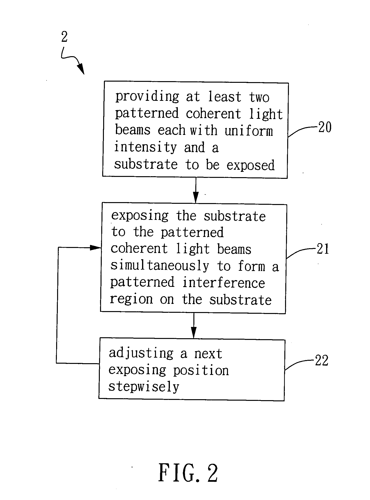
[0011]It is another object of the present invention to provide a method and an apparatus for generating periodic patterns by step-and-align interference lithography, by moving the substrate or the light beams stepwisely to form a patterned region with a large area on the substrate. Thereby, environment can be precisely controlled during exposure to prevent disturbance such as temperature gradient, airflow, humidity and mechanical vibration.

Problems solved by technology

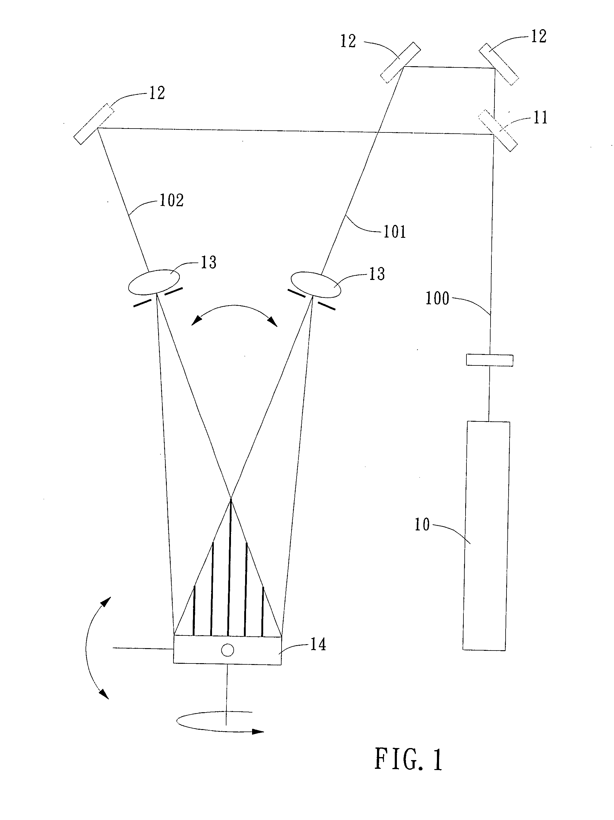
However, in FIG. 1, a large space is required for implementation because it takes a distance (21 meters as disclosed by Andreas Gombert, et al.) long enough for the spherical wave from the point light source to travel and expand to an approximate planar wave.
Moreover, it takes a considerably long exposure time (for hours) to expose the photo-resist because the power per unit area decreases with the distance.
However, in this method, high-precision positioning control is required and the process time is long.
However, since the light intensity profile is a circular Gaussian distribution, uniform exposure dosage is hard to achieve because the areas of overlapped regions after multi-exposure processing are varied.
Moreover, selectivity in photo-resist materials is limited, and the use of the transparent substrate makes the method less compatible with the existing Si-based semiconductor industry.

Method used


Image

  • Method and apparatus for generating periodic patterns by step-and-align interference lithography
  • Method and apparatus for generating periodic patterns by step-and-align interference lithography
  • Method and apparatus for generating periodic patterns by step-and-align interference lithography

Examples


first embodiment

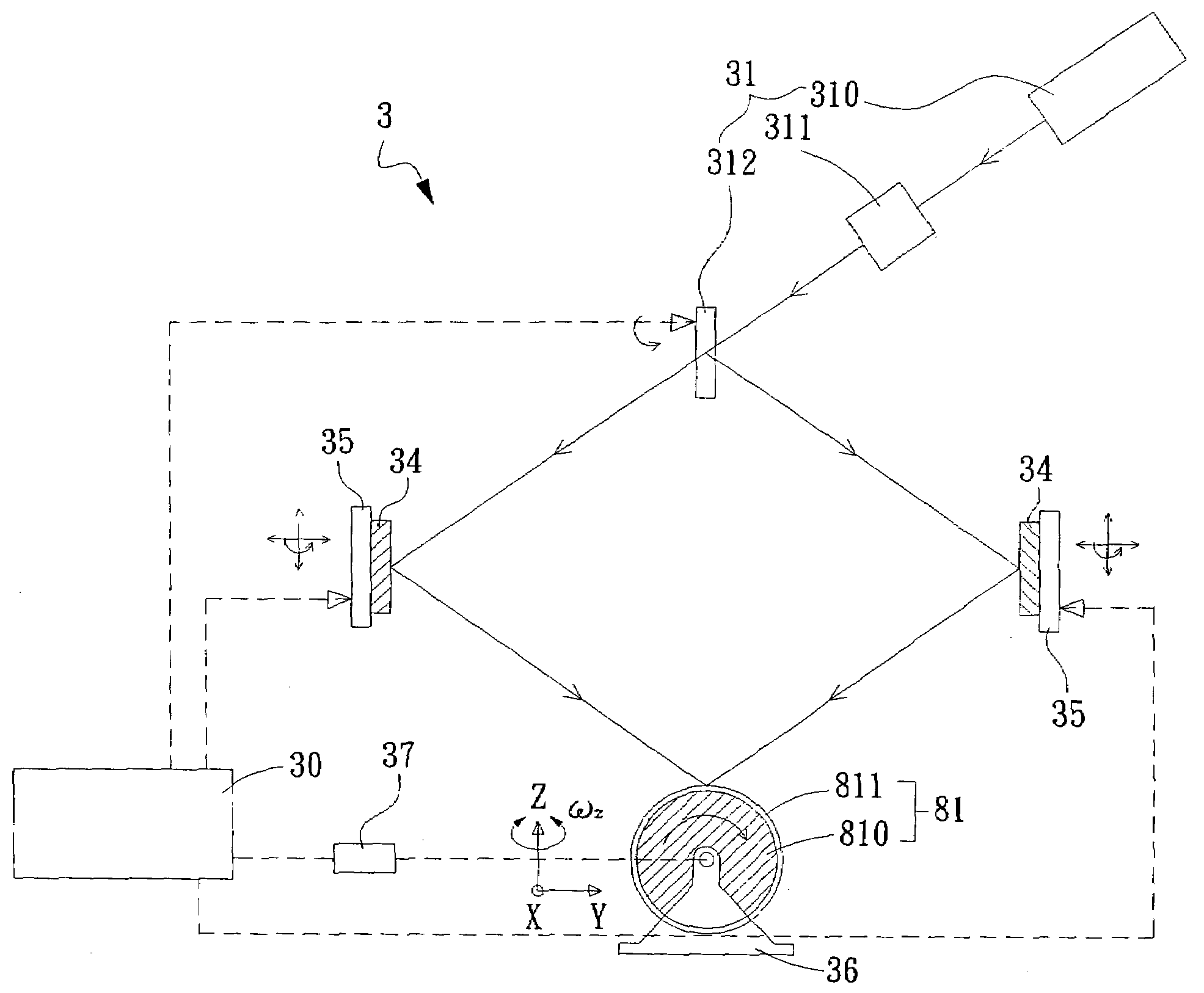
[0033]Please refer to FIG. 5A, which is a schematic diagram showing an apparatus for generating periodic patterns by step-and-align interference lithography according to the present invention. The apparatus 3 comprises a light generating unit 31, a carrier unit 32, and a driver unit 33. The light generating unit 31 is capable of generating at least two coherent light beams with a pattern. The light generating unit 31 further comprises: a beam generator 310, a beam shaper 311 and a beam splitter 312. The beam generator 310 is capable of generating at least a light beam 90. In the present embodiment, the beam generator 310 is a laser generator. The beam shaper 311 is capable of receiving and shaping the light beam 90 to form a shaped light beam 91. The light beam 90 generated from the beam generator 310 has a Gaussian distribution profile and the intensity of the light beam 90 is non-uniform. Therefore, the beam shaper 311 is used to convert the light beam 90 to a shaped light beam 91...

second embodiment

[0039]Please refer to FIG. 7A, which is a schematic diagram showing an apparatus for generating periodic patterns by step-and-align interference lithography according to the present invention. The elements in FIG. 7A are identical to those in FIG. 5A except that the substrate 81 to be exposed carried by the carrier unit 36 is a cylindrical substrate comprising a cylindrical plate 810 with a coating 811 thereon to be exposed. Moreover, the motor unit 37 is exemplified by but not limited to a stepping motor capable of driving the substrate 81 to rotate and driving the carrier unit 36 to move in three dimensions. By controlling the exposure position stepwisely, a large-area interference patterns can be formed on the substrate 81, as shown in FIG. 7B.

[0040]Please refer to FIG. 8, which is a schematic diagram showing a plurality of pairs of coherent light beams incident on a substrate to form large-area periodic patterns. In the present embodiment, the apparatus in FIG. 5A or 7A can be u...


PUM


Abstract

The present invention provides a method and an apparatus for generating periodic patterns by step-and-align interference lithography, wherein at least two coherent light beams with a pattern are controlled to project onto a substrate to be exposed to form an interference-patterned region on the substrate. Thereafter, by means of moving the substrate or the light beams stepwisely, a patterned region with a large area can be formed on the substrate. According to the present invention, the optical path and exposure time may be shortened to reduce defect formation during lithographic processing and to improve the yield.

Description

BACKGROUND OF THE INVENTION[0001]1. Field of the Invention[0002]The present invention generally relates to a method and an apparatus for generating periodic patterns and, more particularly, to a method and an apparatus for generating periodic patterns by step-and-align interference lithography, using at least two coherent light beams with controlled intensity distribution to project onto a photo-resist coated substrate to form an interference-patterned region on the substrate. Thereafter, by means of moving the substrate or the light beams stepwisely, a large area composed of continuous patterned regions can be formed on the substrate.[0003]2. Description of the Prior Art[0004]Interference lithography uses at least two light beams to overlap on a substrate so as to form periodic patterns on the photoresist layer on the substrate. Thereby, periodic micro-scale structures such as lines, holes, rods and the like can be manufactured. Using interference lithography, short wavelength ligh...

Claims


Application Information

Patent Timeline
IPC IPC(8): G03F7/22G03B27/42
CPCG03F7/70408
Inventor WANG, LONCHEN, YUNG-PINJAO, CHIH-SHENGCHANG, SHUO-HUNGCHANG, JER-HAUR
Owner IND TECH RES INST
Learn More