Winged I.V. set

Inactive Publication Date: 2001-04-03
RETRACTABLE TECH INC
View PDF24 Cites 198 Cited by
  • Summary
  • Abstract
  • Description
  • Claims
  • Application Information

AI Technical Summary

Benefits of technology

Additionally, it is important that winged I.V. sets be easily molded on production equipment in large quantities and have few parts. Assembly is equally important because the devices are mass produced and preferably assembled with the aid of machines. The present invention is a significant improvement over the prior art which allows safe, one-handed controlled retraction of the needle directly from the patient without removing the device from its pre-retracted position. The present invention is economical to mass produce and assemble at low cost. The housing can be molded in one piece. The only other part is the retraction body, except for the needle and retraction spring. The present invention offers a significant improvement over the prior art devices and accomplishes all of these objects and more.
A needle bearing retraction body is mounted for sliding movement within the chamber. The retraction body is positionable in an unretracted position in the front portion of the chamber with the needle exposed. The needle extends from the front of the retraction body and would normally be provided with a cap over the needle which is removed by the user just prior to use. The retraction body has a catch portion positionable just ahead of the releasable latch to hold the retraction body in the unretracted position. A biasing element in driving contact with the retraction body tends to drive the retraction body into the rear portion of the chamber in response to release of the releasable latch thereby moving the retraction body into a retracted position with the needle protected. That is, the entire needle is drawn back into the elongated housing when the retraction body moves into the retracted position. A back end portion of the retraction body is provided with a tubing connector in fluid communication with the needle and a length of tubing having one end pushed onto the tubing connector. The tubing extends from an opening in the back of the housing with enough clearance between the tubing and the housing to prevent any interference that might occur during movement of the retraction body. In the usual manner, the free end of the tubing is connected to a fluid reservoir usually through a drip control mechanism which is elevated to deliver fluid to the patient through the device.

Problems solved by technology

A problem occurs upon withdrawal because the needle, now contaminated with blood or other body fluid, must be disposed of without risking needle sticks to medical personnel engaged in the operation of withdrawing the winged I.V. set or to hospital disposal personnel.
Caps or covers that are mounted over the needle are not a satisfactory solution because someone must put them in place and because they can become loose and expose a used needle.
Prior art safety systems for winged I.V. sets are seen to be problematic.
Some of the systems must be threaded into pre-existing winged I.V. sets creating additional difficulties for healthcare workers prior to insertion of the needle.
They also open the possibility for additional error if improperly put in place.

Method used


Image

  • Winged I.V. set
  • Winged I.V. set
  • Winged I.V. set

Examples


Embodiment Construction

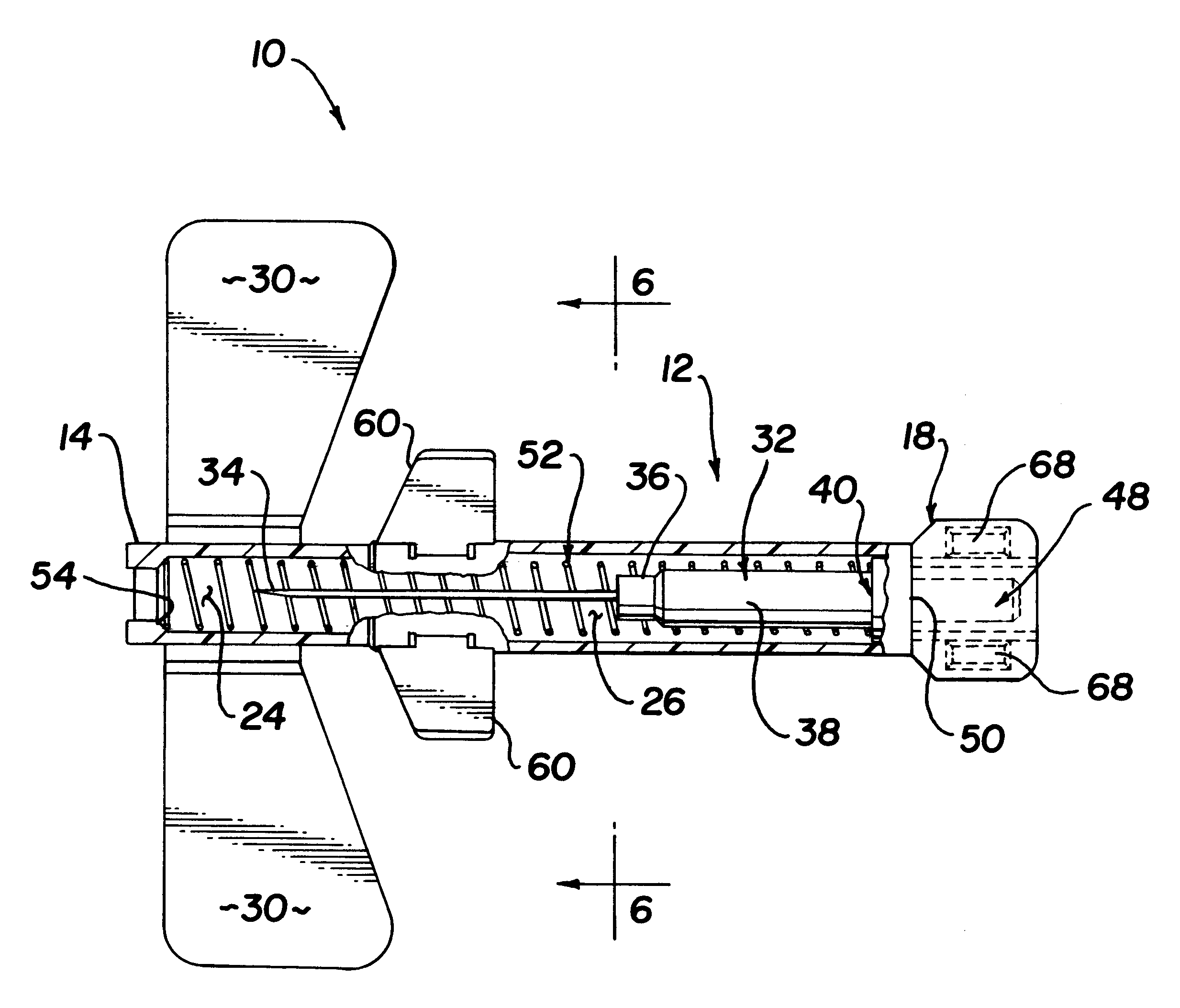
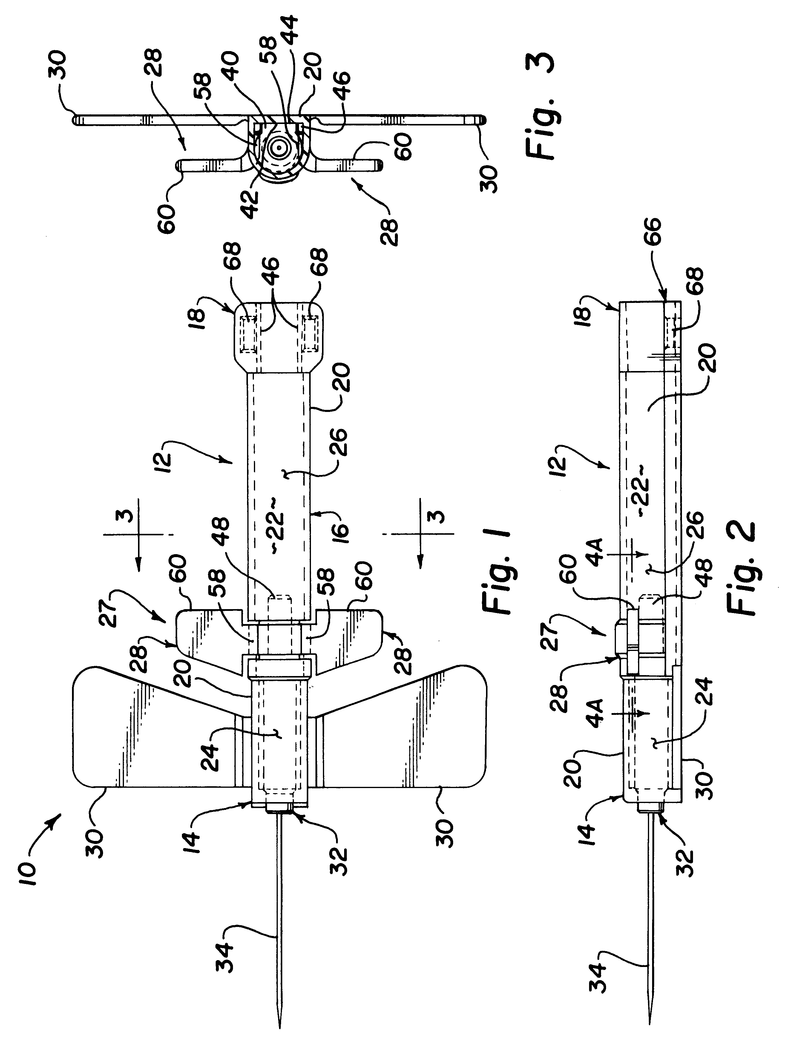
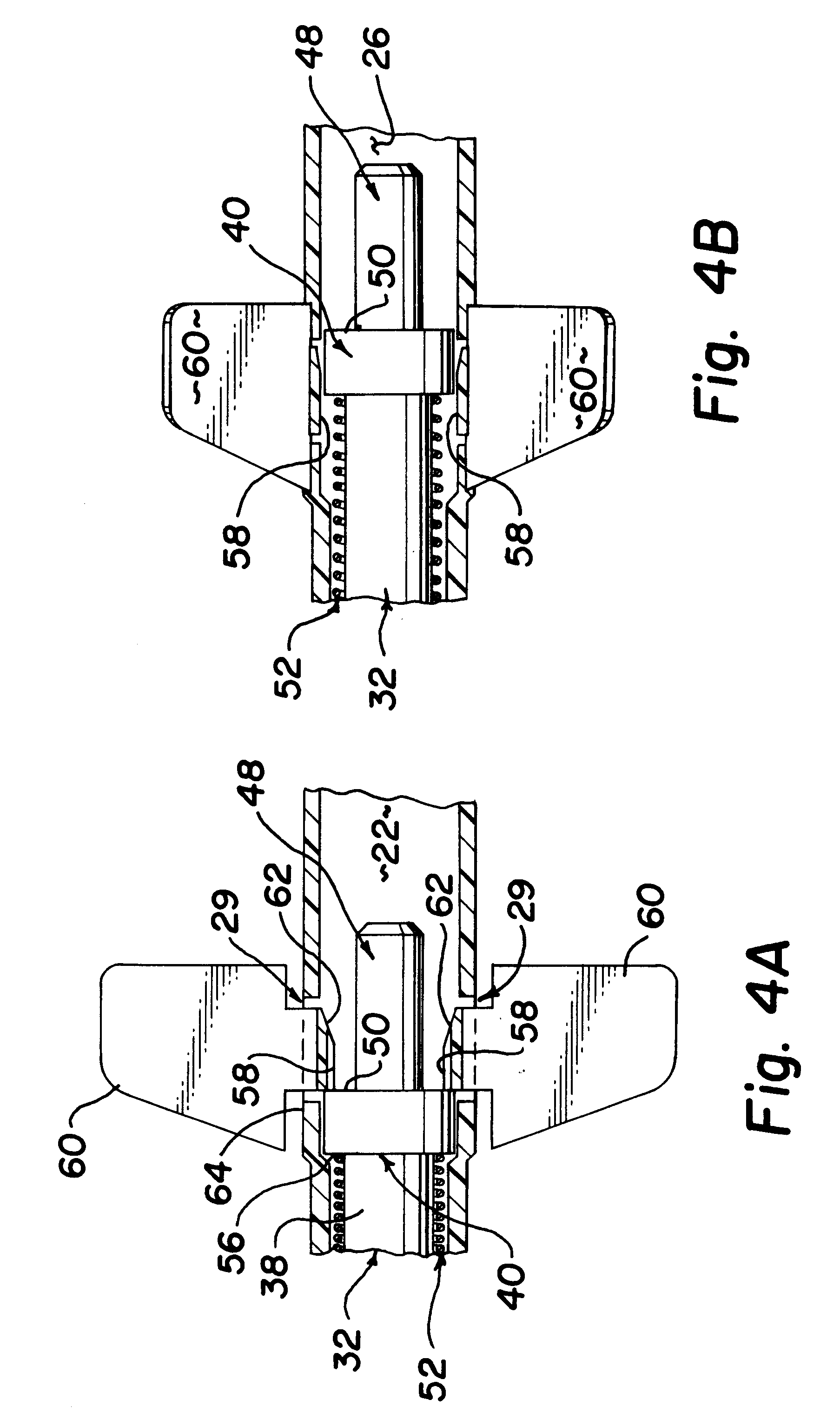
In FIG. 1, the retractable winged I.V. apparatus is referred to generally by the reference numeral 10. Winged apparatus 10 has an elongated housing 12 having a front end 14 and a back end 18. Elongated housing 12 has an elongated wall 20 and a hollow chamber 22 extending from front end 14 to back end 18. Hollow chamber 22 is divided into a front portion 24 and a rear portion 26 separated by a releasable latch 28.

Wings 30 are attached to wall 20 of body 12 near front 14. Wings 30 are designed to be bendable to some extent to conform to a patient's arm. They are used with tape to hold the I.V. set in place after the vein has been punctured. As will be seen, the apparatus 10 can be retracted without removing the tape or the device from the patient.

A retraction body 32 is mounted for sliding movement within chamber 22. Retraction body 32 is positionable in front portion 24 of the chamber 22 with a hollow needle 34 exposed in front of body 12 for use. A fluid path (not illustrated) exten...


PUM


Abstract

A retractable winged I.V. set has a slidable retraction body mounted in a hollow chamber of a housing. The retraction body has a hollow needle fixed in its front end and a tube connector for passing fluid from an external reservoir through the needle. The housing has a pivoting releasable latch preferably configured as dual opposed latches that are biased to normally encroach into the chamber through an opening in the wall of the housing. A catch portion on the retraction body is contacted by an encroaching latch portion to hold the retraction body in an unretracted position with the needle exposed for use. When the latches are released, a spring drives the retraction body to the back of the chamber and withdraws the needle into the housing.

Description

The invention is a medical device to make a temporary intravenous patient connection.BACKGROUND OF THE PRIOR ARTI.V. sets are well-known in the art for delivering intravenous fluid to a patient by means of a needle connected through a winged body. They are designed to be temporarily installed to deliver fluid directly to the patient's vein through the extended needle. The wings are used to handle the assembly during insertion and withdrawal and to stabilize the device. The wings provide a broad contact area which allows taping the device to the patient while discouraging movement, especially any rotation, of the device.A problem occurs upon withdrawal because the needle, now contaminated with blood or other body fluid, must be disposed of without risking needle sticks to medical personnel engaged in the operation of withdrawing the winged I.V. set or to hospital disposal personnel. Caps or covers that are mounted over the needle are not a satisfactory solution because someone must p...

Claims


Application Information

Patent Timeline
IPC IPC(8): A61M25/06A61M5/32
CPCA61M25/0631A61M25/0637A61M5/3257
Inventor SHAW
Owner RETRACTABLE TECH INC
Why Eureka
Try Eureka