Systems and methods for reducing detected intensity non uniformity in a laser beam

a laser beam and detected intensity technology, applied in the field of lasers, can solve the problems of increasing the detection spatial uniformity of the diode laser, increasing the cost of gas lasers, and reducing the effect of vibration

Inactive Publication Date: 2008-12-18
FLUIDIGM CORP
View PDF99 Cites 1 Cited by
  • Summary
  • Abstract
  • Description
  • Claims
  • Application Information

AI Technical Summary

Benefits of technology

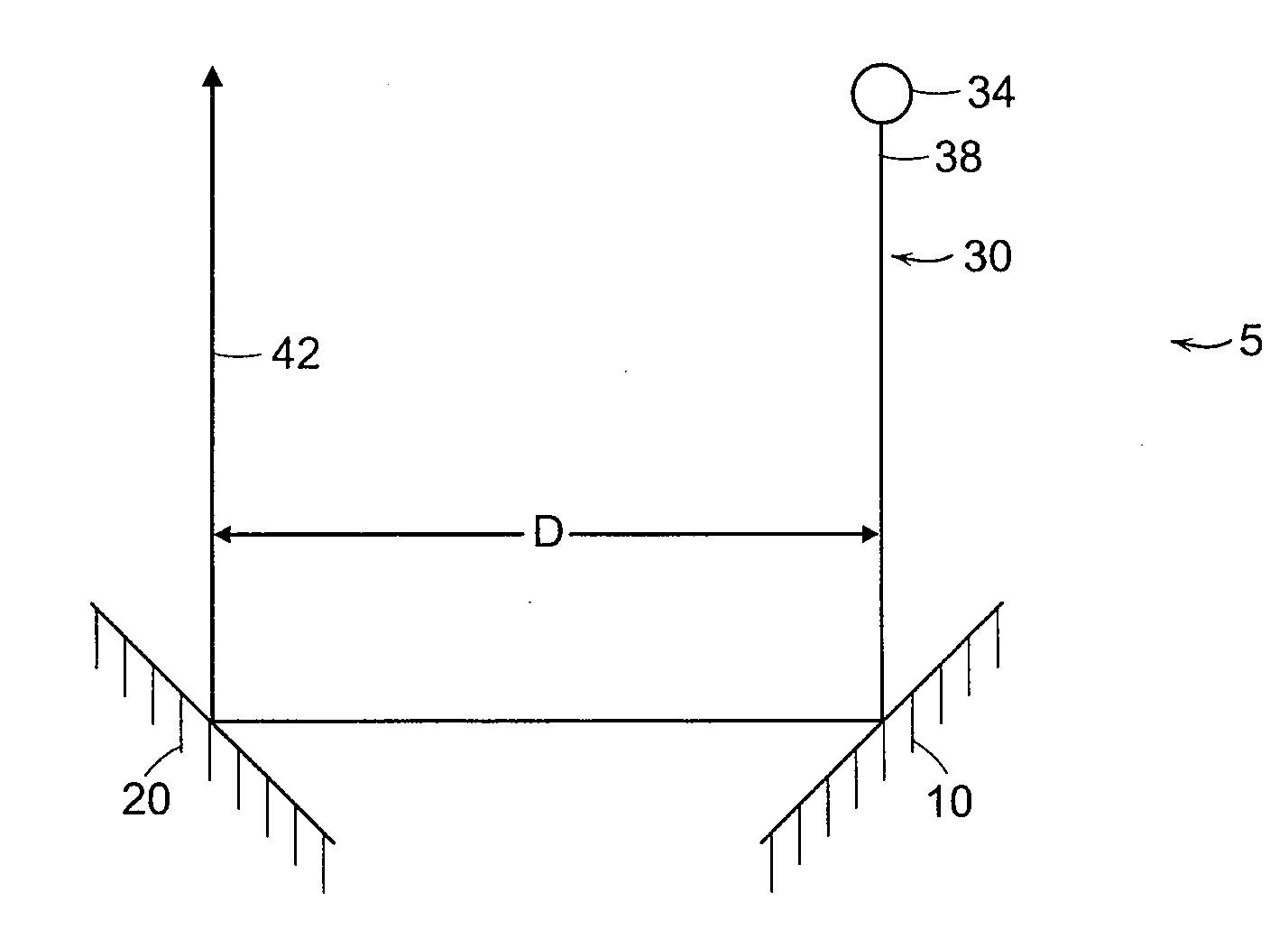
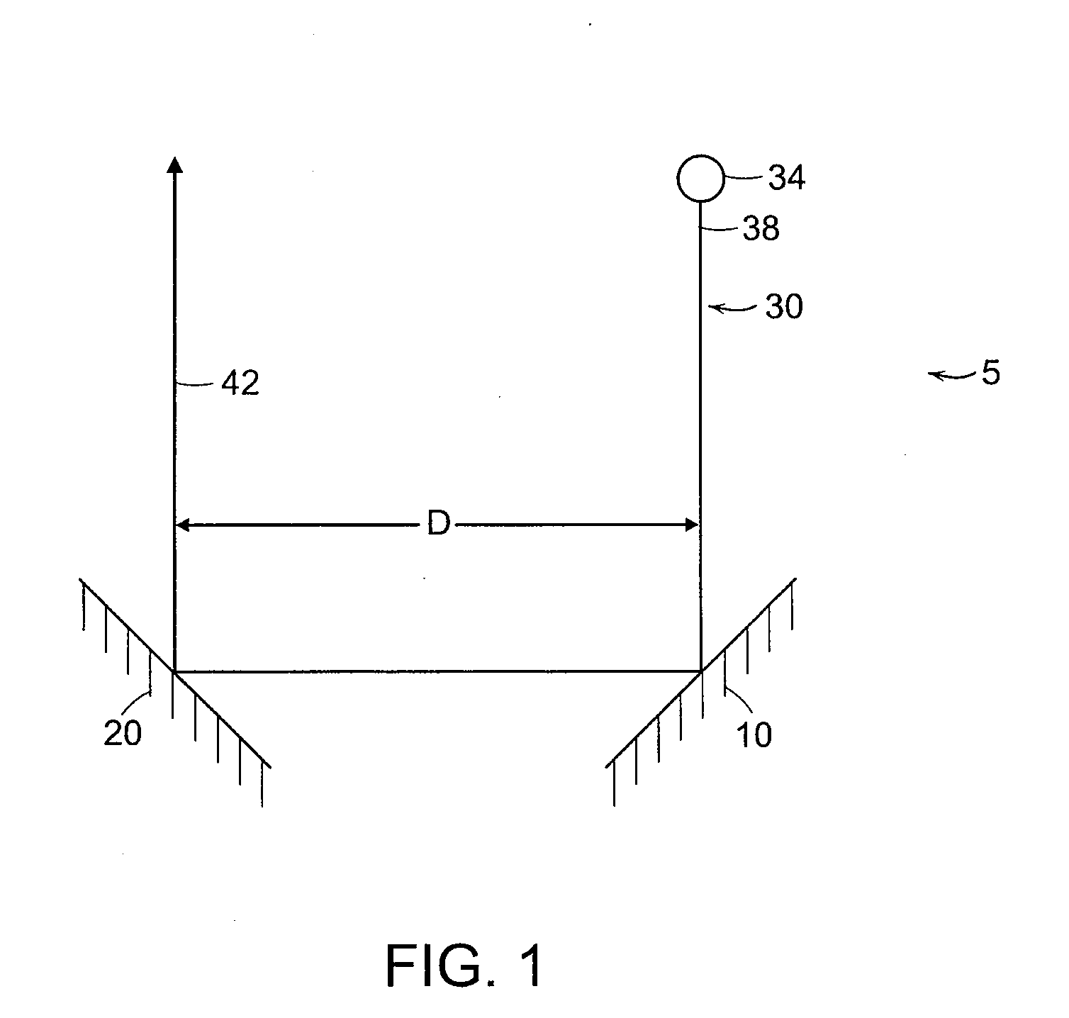
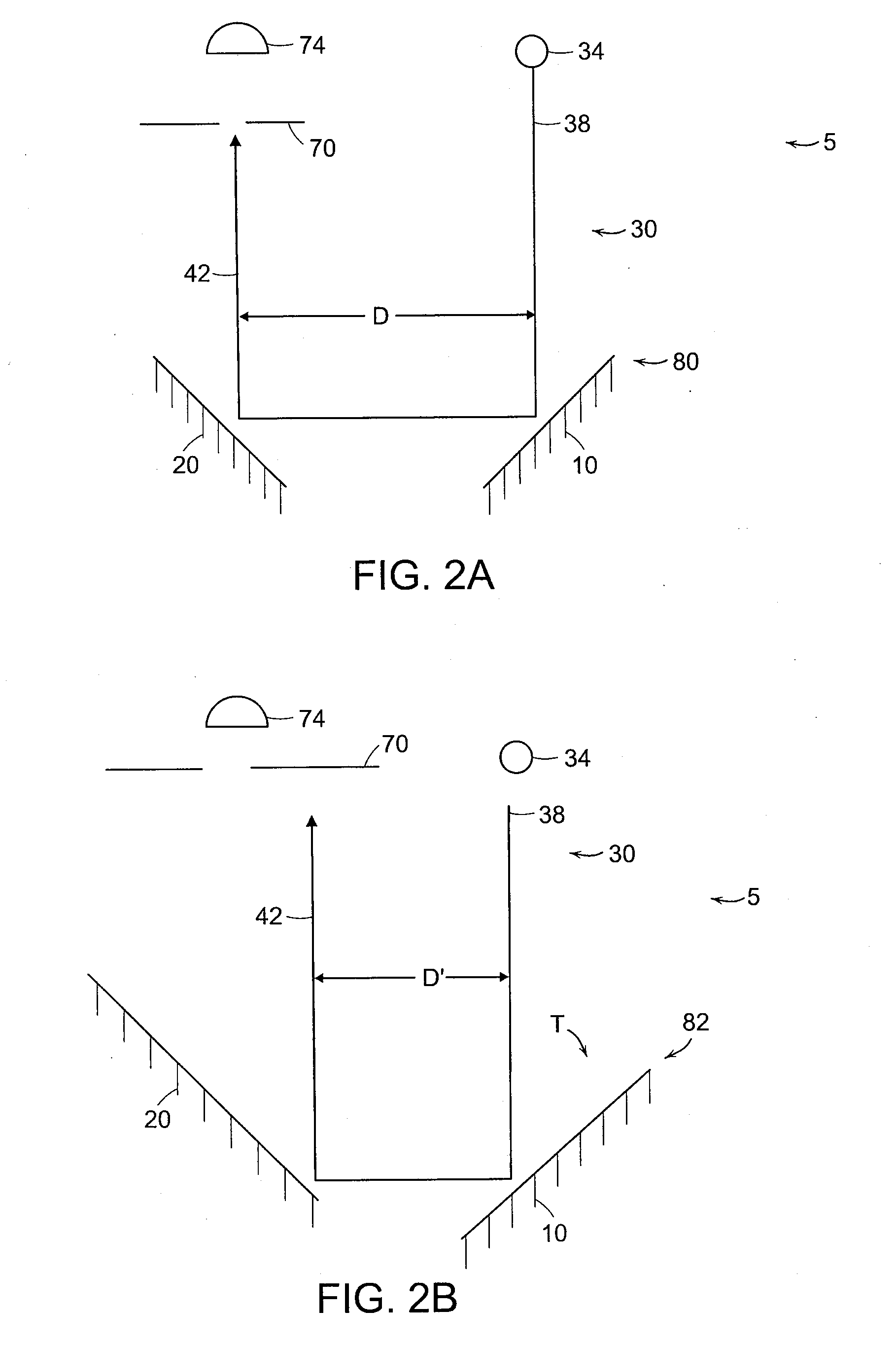
[0013]In another embodiment, a system for increasing the detected spatial uniformity of a diode laser comprises mounting the central axis of a retroreflector eccentric to a mechanical axis of rotation. As the retroreflector is rotated about the mechanical axis, an incoming beam of light is swept through a circle of twice the radius of the eccentricity. The same effect as described above is obtained as high-frequency illumination of the exit beam is reduced in favor of spatially uniform frequencies.
[0014]In another embodiment, set screws are used to balance the retroreflector such that vibration is reduced or eliminated. This also contributes to beam uniformity. An exemplary device is shown in FIGS. 9-11.

Problems solved by technology

The beam produced by the laser diode facet is not uniform in intensity across the radiating facet.
Because of the lack of uniformity in beam intensity, laser diodes diodes conventionally have been viewed as not appropriate for applications where beam intensity uniformity is required.
Therefore, in applications in which high power and uniformity are required other lasers such as gas lasers, which are more expensive and quite large, are generally used.
In many applications, decreasing the cost and size of the laser greatly decreases overall equipment and hence research costs.
Thus, a method or system to decrease the detected non-uniformity in the intensity of a diode laser beam could increase the efficiency and decrease the size of the equipment used in selected applications.

Method used


Image

  • Systems and methods for reducing detected intensity non uniformity in a laser beam
  • Systems and methods for reducing detected intensity non uniformity in a laser beam
  • Systems and methods for reducing detected intensity non uniformity in a laser beam

Examples


Embodiment Construction

[0028]The present invention will be more completely understood through the following detailed description, which should be read in conjunction with the attached drawings. In this description, like numbers refer to similar elements within various embodiments of the present invention. Within this detailed description, the claimed invention will be explained with respect to preferred embodiments. However, the skilled artisan will readily appreciate that the methods and systems described herein are merely exemplary and that variations can be made without departing from the spirit and scope of the invention.

[0029]In general, the solution to the problem of spatial non-uniformity in the detected intensity of the light beam from a laser is to move the light beam, which typically is larger than the detector, and the detector relative to each other such that the detector “sees” the spatial variations in the intensity of the beam as it crosses the detector and averages them. One way to produce...


PUM


Abstract

A method of increasing the spatial uniformity of the detected intensity of a beam of light from a laser in a system including the laser and a light detector. In one embodiment the method includes the steps of generating a beam of light with the laser; and moving the beam of light and the light detector relative to each other, such that the detector averages the spatial intensity of the beam of light over time. In another embodiment the invention relates to a system for increasing the detected spatial uniformity of the intensity of a beam of light. In one embodiment the system comprises a light detector; a laser source for generating the beam of light; and a means for moving the beam of light and the detector relative to one another such that the detector averages the intensity of the light beam over time.

Description

RELATED APPLICATIONS[0001]This Application is a continuation-in-part of U.S. Ser. No. 11 / 370,605, filed on Mar. 8, 2006.FIELD OF THE INVENTION[0002]The present invention relates to lasers, and specifically to improved methods for reducing detected intensity non-uniformity in a laser beam.BACKGROUND OF THE INVENTION[0003]Many measurements require the use of a laser as a source of light. For example, lasers are used in systems ranging from simple object imaging to the detection of nucleotides in sequencing-by-synthesis reactions. In such systems various types of lasers are used, including gas lasers, chemical lasers, excimer lasers, solid-state lasers, semiconductor lasers (including diode lasers), dye lasers and hollow cathode sputtering metal ion lasers. Each type of laser has its own set of advantages and disadvantages when used for a specific application. For example, the characteristics of the different types of lasers including power output, wavelength, cost, size, tenability an...

Claims


Application Information

Patent Timeline
Patent Type & Authority Applications(United States)
IPC IPC(8): G01J1/00
CPCG01J1/4257G01J2001/4261G02B27/0933
Inventor WEBER, AARONTRACY, DAVID H.
Owner FLUIDIGM CORP
Why Eureka
Try Eureka