Exhaust purification device for internal combustion engine
a technology for purifying devices and internal combustion engines, applied in the direction of exhaust treatment electric control, electrical control, separation process, etc., to achieve the effect of reducing catalysts and more accurate obtainmen
- Summary
- Abstract
- Description
- Claims
- Application Information
AI Technical Summary
Benefits of technology
Problems solved by technology
Method used
Image
Examples
first embodiment
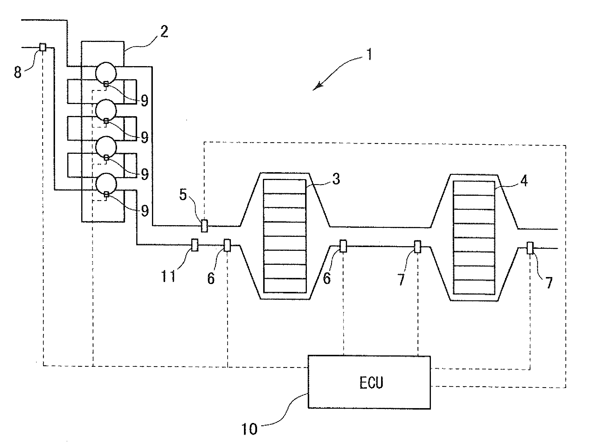
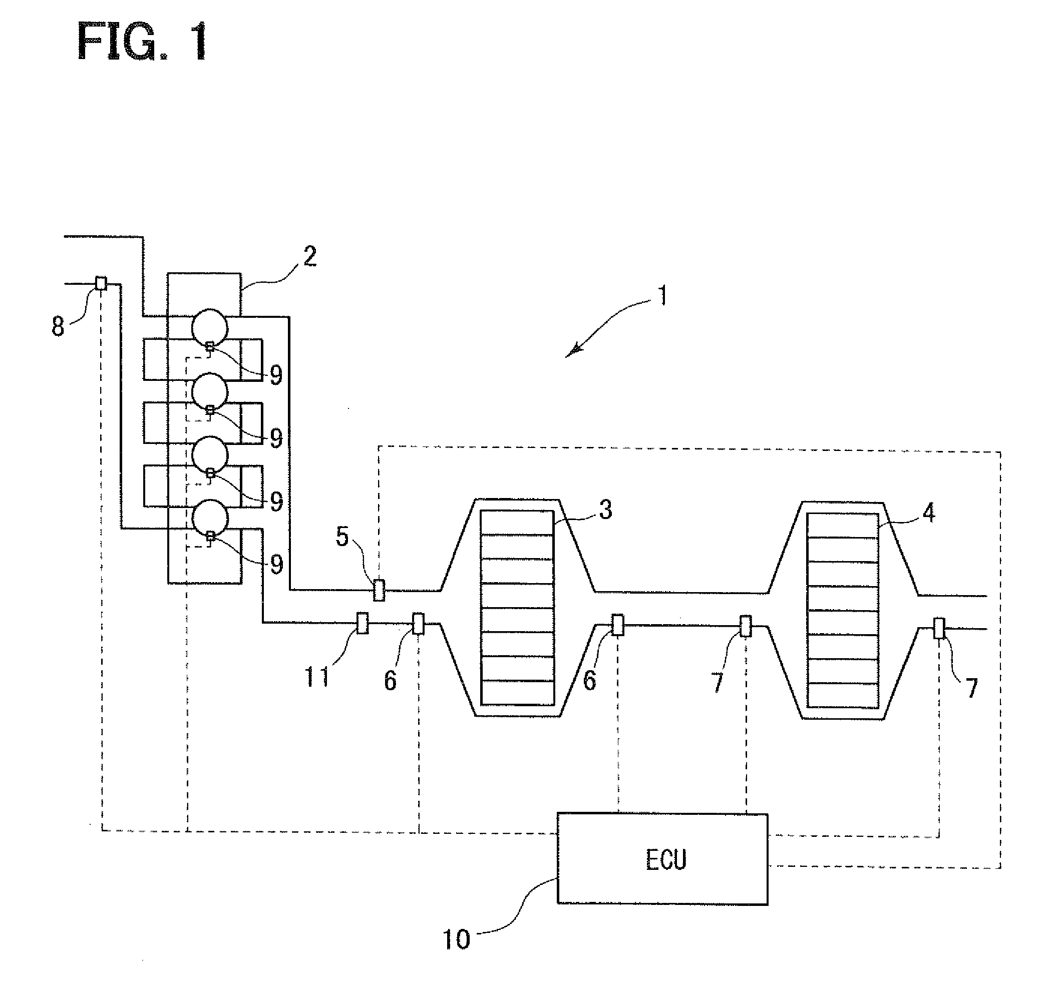
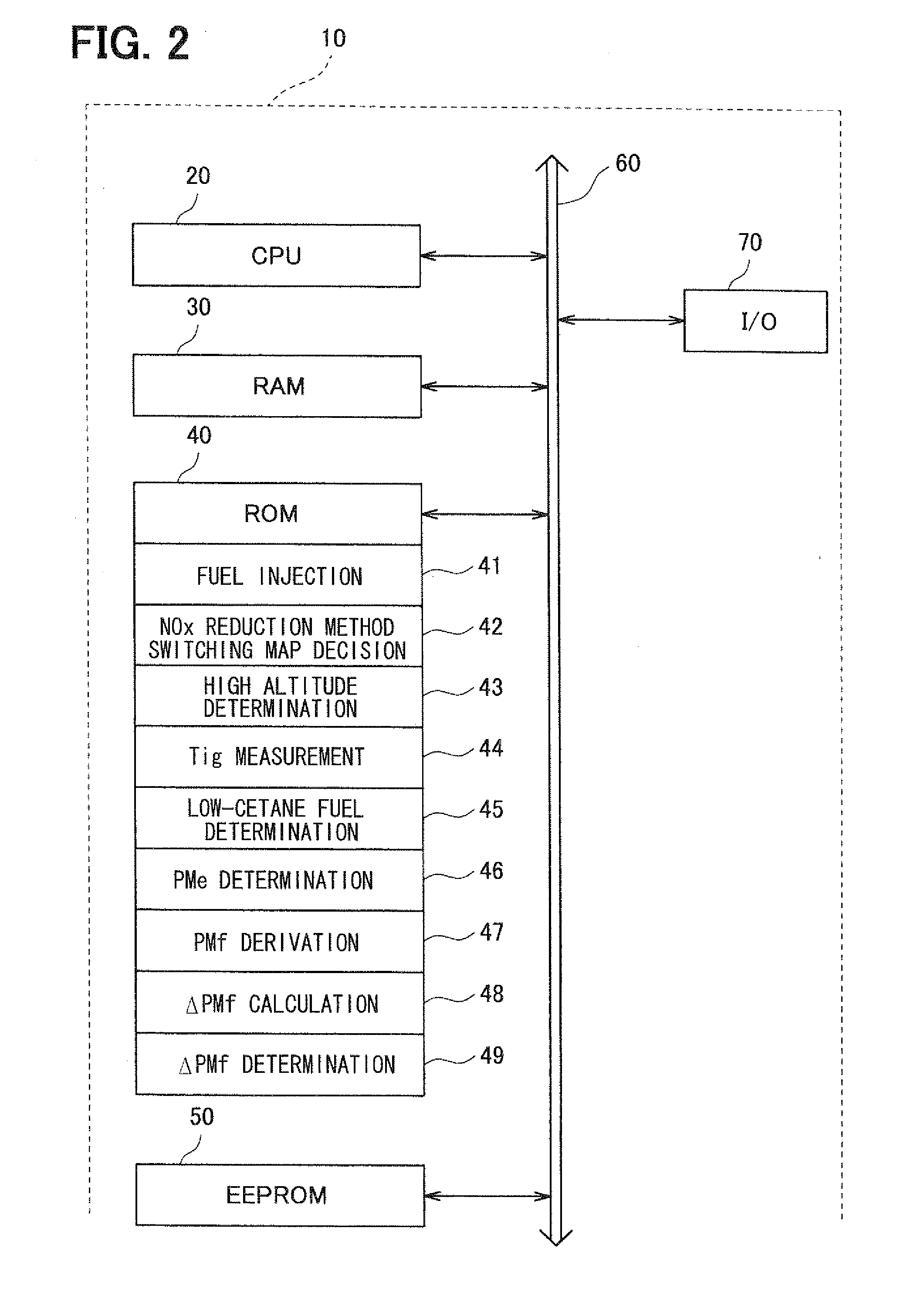
[0031]FIG. 1 is a system diagram showing an exhaust purification device of an internal combustion engine 1 according to the present invention. A diesel engine 2 shown in FIG. 1 serves as a motor. A diesel particulate filter 3 (DPF) as a filter section for collecting particulate matters contained in exhaust gas of the diesel engine 2 is arranged in a passage on an exhaust side of the diesel engine 2. Further, a Lean NOx trap 4 (hereinafter, referred to as LNT) as a catalyst of a NOx occlusion reduction type for removing nitrogen oxides (NOx) contained in the exhaust gas is arranged downstream of the DPF 3. The NOx occlusion reduction type catalyst occludes the NOx when an oxygen concentration of the exhaust gas is high and discharges the NOx when the oxygen concentration of the exhaust gas is low. The NOx performs an oxidation-reduction reaction with HC or CO contained in the exhaust gas when discharged and is oxidized or reduced to CO2, H2O and N2. The NOx in the exhaust gas is remo...
second embodiment
[0057]FIG. 5 is a flowchart showing an example of switching processing of the NOx reduction method according to the present invention. First, the ECU 10 measures the discharge quantity PMe of the smoke with the smoke sensor 11 and receives the measurement value in S200.
[0058]Then, the ECU 10 determines whether the measured discharge quantity PMe of the smoke is equal to or greater than the first predetermined value α in S210. When the discharge quantity PMe of the smoke is equal to or greater than the first predetermined value α (S210: YES), the ECU 10 determines that a large quantity of the smoke is generated and switches the switching map of the NOx reduction method or rewrites the map values so that the area for performing the rich combustion changes toward the low rotation and low load area side in S220. Then, the switching processing of the NOx reduction device is ended.
[0059]When the discharge quantity PMe of the smoke is less than the first predetermined value α (S210: NO), t...
third embodiment
[0061]FIG. 6 is a flowchart showing an example of switching processing of the NOx reduction method according to the present invention. First, the ECU 10 measures the differential pressure ΔP between the inlet and the outlet of the DPF 3 with the differential pressure sensors 6 and receives the measurement value ΔP in S300. Then, the ECU 10 calculates the particulate matter deposition quantity PMf from the measurement value ΔP in S310.
[0062]Then, the ECU 10 calculates an increase degree ΔPMf of the particulate matter deposition quantity PMf in S320. The increase degree ΔPMf of the particulate matter deposition quantity PMf is calculated from the particulate matter deposition quantity PMf and a travel distance. The increase degree ΔPMf may be calculated from the particulate matter deposition quantity PMf and a travel period.
[0063]Then, the ECU 10 determines whether the calculated increase degree ΔPMf of the particulate matter deposition quantity PMf is equal to or greater than the sec...
PUM
 Abstract
Description
Claims
Application Information
 - R&D
- Intellectual Property
- Life Sciences
- Materials
- Tech Scout
- Unparalleled Data Quality
- Higher Quality Content
- 60% Fewer Hallucinations
Browse by: Latest US Patents, China's latest patents, Technical Efficacy Thesaurus, Application Domain, Technology Topic, Popular Technical Reports.
© 2025 PatSnap. All rights reserved.Legal|Privacy policy|Modern Slavery Act Transparency Statement|Sitemap|About US| Contact US: help@patsnap.com


