
Apparatus and Method for Purification and Disinfection of Liquid, Solid or Gaseous Substances

a technology of apparatus and liquid, which is applied in the direction of disinfection, crystal growth process, energy-based chemical/physical/physico-chemical processes, etc., can solve the problems of hampered efficiency of agents in killing non-bacterial species, inability to achieve sufficient mixing of active species and liquid phase to be treated, and the inability to eliminate a wide variety of residual micropollutant species using these techniques

Active Publication Date: 2008-11-27
VLAAMSE INSTELLING VOOR TECHNOLOGISCH ONDERZOEK NV VITO
View PDF10 Cites 52 Cited by
  • Summary
  • Abstract
  • Description
  • Claims
  • Application Information

AI Technical Summary

Benefits of technology

The present invention is about an apparatus and method that uses a combination of plasma and photo-catalysis to achieve a synergistic effect on disinfection and purification of water and air. The method involves generating plasma in a gaseous phase and mixing it with a liquid phase, where UV and visible light produced during the plasma discharge can induce photo-catalysis. The apparatus is modular and can be easily up-scaled to meet higher throughput requirements. The invention also utilizes the synergy between plasma and photo-catalysis to regenerate the catalyst and reduce energy consumption. The efficiency and efficacy of treatment can be influenced by the distance between the generated plasma and the catalyst surface and the spectral characteristics of the plasma and the absorbance of the light by the matrices it encounters. The invention can also use UV and visible light-transparent phase-separators to further exploit the synergy of plasma and photo-catalysis.

Problems solved by technology

The problem usually is to produce a homogeneous dielectric barrier discharge plasma with sufficient surface area in or above a liquid phase layer.
However, to achieve sufficient mixing of these active species with the liquid phase that is to be treated is often a problem.
Although some toxic organic compounds may be destroyed using either Corona treatment or UV photo-catalysis, a wide variety of residual micropollutant species cannot be eliminated using these techniques.
Known drawbacks are that such agents often are hampered in their efficiency to kill non-bacterial species or cause the formation of undesired side products such as organic halogens subject to absorption (AOX) through interaction of e.g., chlorine with organic matter in water.
Furthermore, chlorine and biocides have a negative impact on the quality of drinking water.
Also some rest chemical oxygen demand (COD) can cause in certain niches post-growth of bacteria and may lead to infection and fouling of equipment and utilities.
A number of technical problems are identified regarding the use of submerged plasma technology aimed at disinfection and purification of liquids, such as e.g., water, and also gases, such as e.g., air.
A first problem is how to generate a dielectric barrier discharge (DBD) plasma in a gaseous phase which is submerged into or surrounded by a liquid phase.
A second problem related to the use of plasma technology that is directed towards disinfection and purification of liquid or gaseous media is often posed in the requirement for industrial capacity.
Using state-of-the art treatment equipment, practical limitations are often observed with flow rates of substrate liquid or gas streams.
As a consequence, energy costs of operation and up scaling costs to meet capacity requirements may be high.
A problem associated with photo-catalyzed micropollutant removal processes is the degeneration of the catalyst that is used.
This requires regeneration, or sometimes even replacement, of the catalyst involving downtime and extra costs for replacement of the catalyst.
This technique has a number of drawbacks, the main one being a loss of power due to the existence of current in the water.
This system also suffers from the fact that the flow of liquid through the apparatus is subjected to considerable flow restrictions, which puts a limit on the possible flow rates which can be processed.
This system is also difficult to up-scale, due to its specific geometry, wherein the electrical field is coaxial to the flow direction of the treated liquid.

Method used


Image

  • Apparatus and Method for Purification and Disinfection of Liquid, Solid or Gaseous Substances
  • Apparatus and Method for Purification and Disinfection of Liquid, Solid or Gaseous Substances
  • Apparatus and Method for Purification and Disinfection of Liquid, Solid or Gaseous Substances

Examples


Embodiment Construction

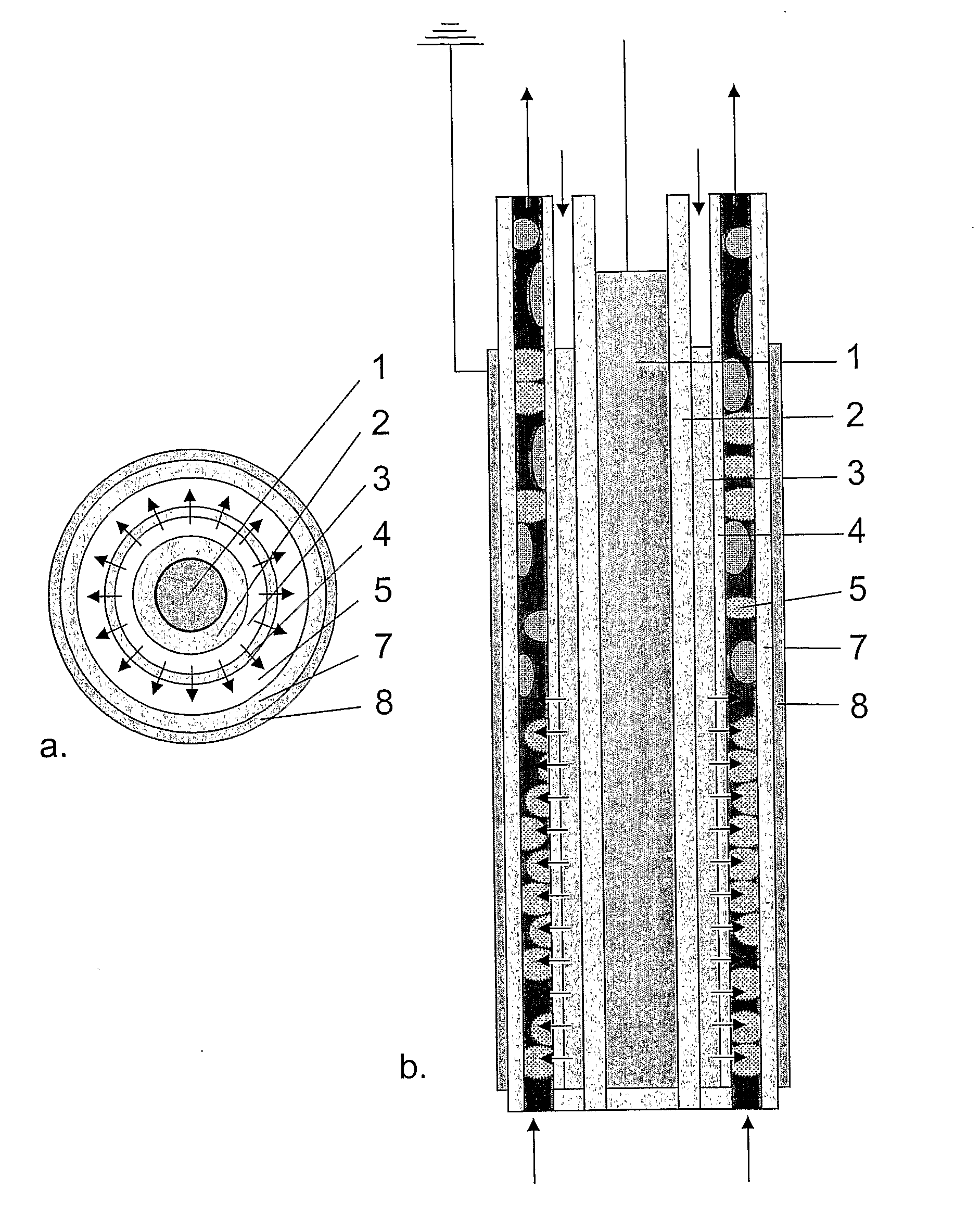
[0022]The invention is related to an apparatus for disinfection and purification of a medium comprising a liquid, gaseous or solid phase, or a mixture thereof, and to a method performed with said apparatus, in which plasma is generated under atmospheric conditions in a first medium which is preferably a gaseous phase, such as e.g., air, which is then introduced by injection into a second medium, which is preferably a liquid phase, such as e.g., water, in such a way, that a mixing flow between the first and the second medium is established and the plasma is utilized to disinfect and purify the first and / or the second medium.

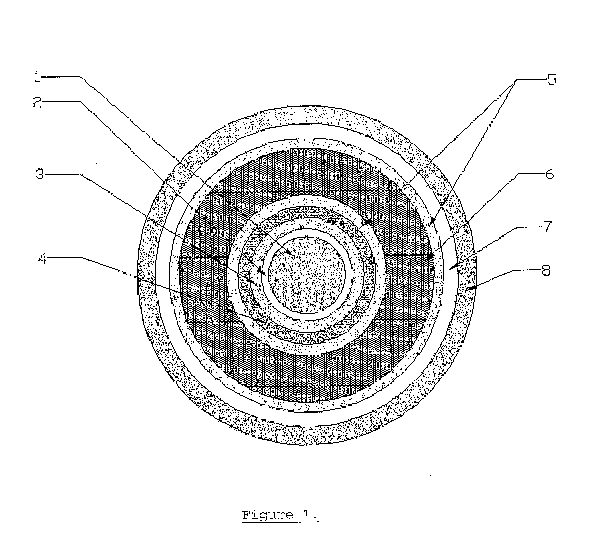
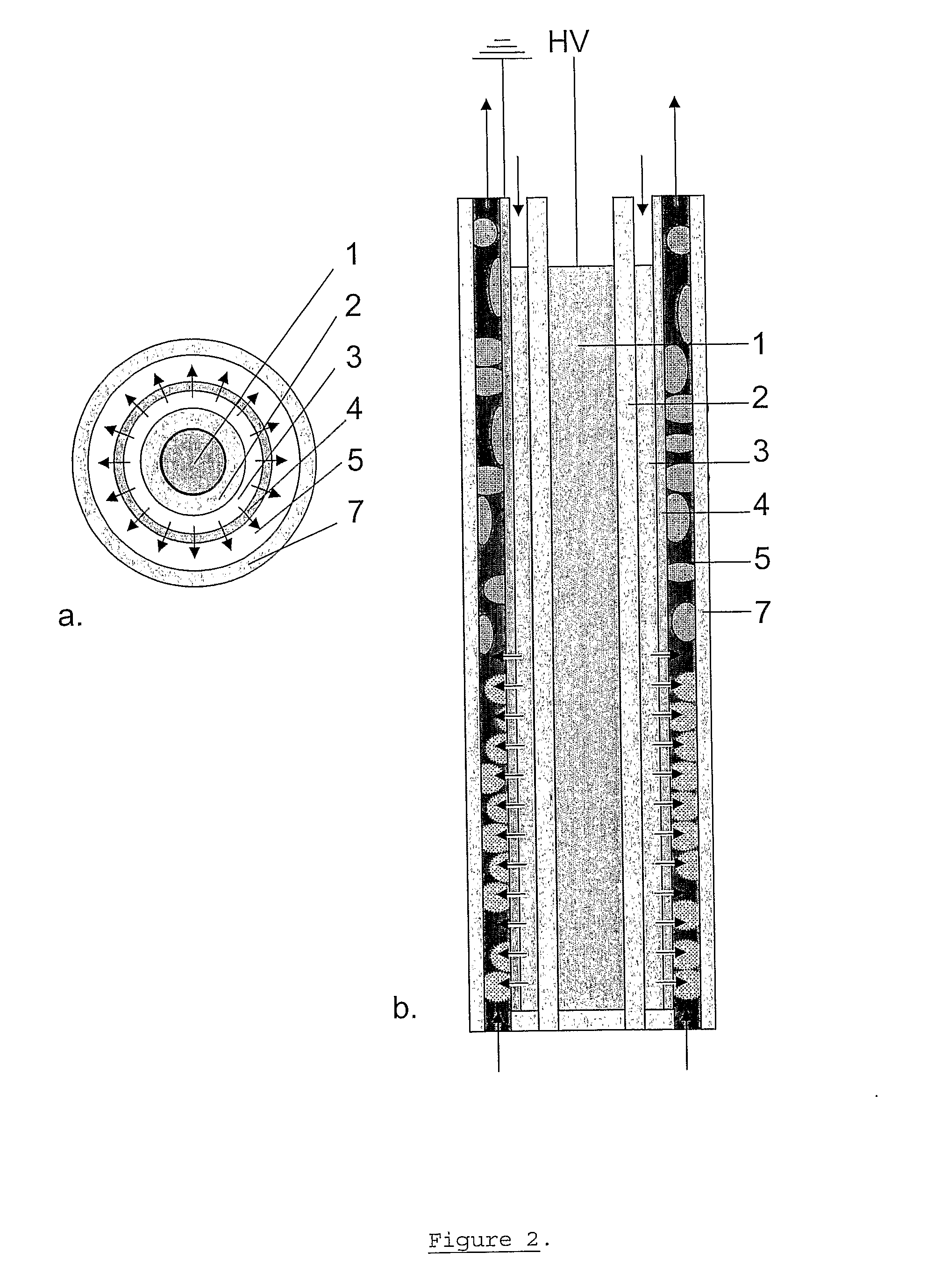
[0023]FIG. 1 shows a cross-section of a first embodiment of the apparatus of the invention, hereafter also called a reactor, having a tubular geometry. Other geometries are equally possible, however, such as the planar (flat panel) geometry shown in FIG. 6-9. The geometries of FIGS. 1-6 are symmetric, comprising a central round or flat electrode surrounded by a nu...


PUM

PropertyMeasurementUnit
breakdown voltageaaaaaaaaaa
voltageaaaaaaaaaa
areaaaaaaaaaaa

Abstract

An apparatus and method are for disinfection and purification of a liquid, gaseous or solid phase, or a mixture thereof. The apparatus includes: a central electrode, a dielectric layer adjacent to the electrode, a first area adjacent to the dielectric layer, and is configured to introduce a first medium into the first area, a second area adjacent to the first area. The apparatus is also configured to introduce a second medium into the second area, and for creating a plasma in the first medium, while the first medium is present in the first area, by applying a voltage between the first electrode and a second electrode. An injector injects the plasma into the second area, in order to be mixed with the second medium.

Description

FIELD OF THE INVENTION[0001]The present invention is related to the use of atmospheric plasma and chemical photo-catalysis technology for treatment of liquids and / or gases. The invention is of interest in the fields of disinfection and purification of drinking water and industrial waste water, antifouling of industrial cooling water systems, remediation of polluted surface and ground water sites, bio-farming including hydro-culturing, and cleaning and disinfection of domestic and recreational water systems, such as e.g., swimming pools, showers and jacuzzis, ponds, etc.[0002]Additionally the invention can be applied for the disinfection, cleaning and purification of gases, such as e.g., air, in domestic and industrial air-conditioning and air-treatment systems.BACKGROUND OF THE INVENTION[0003]Plasma technology has been pursued for treatment of liquids, such as e.g., water, for some time (Hoeben, 2000; Lee & Lee, 2003; Yamabe et al., 2004; Grabowski et al., 2004; Lambert & Kresnyak, ...

Claims


Application Information

Patent Timeline
Patent Type & Authority Applications(United States)
IPC IPC(8): A61L2/14
CPCA61L2/10A61L2/14A61L9/16A61L9/22C02F1/325C02F1/46109C02F1/48C02F1/725C02F2001/46152C02F2103/42C02F2305/10
Inventor VANGENEUGDEN, DIRKREGO, ROBBYHAVERMANS, DANNYBLOK, HERMAN
Owner VLAAMSE INSTELLING VOOR TECHNOLOGISCH ONDERZOEK NV VITO
Learn More