
Optical Information Recording Medium and Method for Recording to the Same

a technology of optical information and recording medium, applied in the field of optical information recording, can solve the problems of deterioration of recording signal quality, longer film formation period, and higher production cos

Inactive Publication Date: 2008-11-20
PANASONIC CORP
View PDF4 Cites 0 Cited by
  • Summary
  • Abstract
  • Description
  • Claims
  • Application Information

AI Technical Summary

Benefits of technology

"The present invention provides an optical information recording medium that has good corrosion resistance, recording / reproducing properties, and is suitable for practical use. It includes a substrate with a guide groove, a reflective layer, a light-absorbing layer, a reflected light side protective layer, a recording layer with optical properties that are transformed reversibly due to irradiation with laser light, an incident light side protective layer with a film thickness of ≦50 nm, a resin layer, and a transparent substrate that is irradiated with laser light. The incident light side protective layer includes a plurality of material layers, and among this plurality of material layers, a layer that constitutes an incident light side material layer which is the most closest to the transparent substrate possess minimum internal stress."

Problems solved by technology

Consequently, the period of time for forming the film becomes longer, which is a problem with regard to the production cost becoming higher.
However, since the separation between recording layer 104 and transparent substrate 101 becomes narrower, when repeated recording is carried out, transparent substrate 101 can be damaged by heat from heated recording layer 104, and there is a problem with deterioration of quality in the recording signal.
However, in the abovementioned conventional optical information recording media, since the film thickness of the incident light side protective layer would be thinner, the corrosion resistance of the recording medium would deteriorate readily, and in addition, since the thermal conductivity of the material of the protective layer would be relatively high, high laser power would be necessary when recording.
Additionally, when this recording medium is recorded / reproduced with a relative linear speed between an optical head and a recording medium of 8-12 m / s, which is a normal rotational speed, the resin layer will readily suffer heat damage since the laser light irradiation time will be relatively long, and there will be a problem with deterioration of the recording signal quality.

Method used


Image

  • Optical Information Recording Medium and Method for Recording to the Same
  • Optical Information Recording Medium and Method for Recording to the Same
  • Optical Information Recording Medium and Method for Recording to the Same

Examples


embodiment 1

[0032]A recording medium comprises at least a reflective layer, a light-absorbing layer, a reflected light side protective layer, a recording layer, an incident light side protective layer, a resin layer and a transparent substrate in the sequence above a substrate.

[0033]The substrate has a guide groove in order to guide the laser light. As the material, a resin such as PM A, or glass or the like can be used. In addition, the substrate is formed with alternating groove portions and land portions. Furthermore, substrates with different ratios for the widths of groove portion and the land portion can be used. Although there is no particular limitation on the film thickness for the substrate, a value ≧0.1 mm and ≦1.2 mm is preferred. If the film thickness is ≧0.1 mm, it becomes easier to suppress heat damage during formation of the thin film, and if the film thickness is ≦1.2 mm, the portability of the recording medium can be ensured.

[0034]The reflective layer is composed of a material...

embodiment 2

[0051]Next, an example will be mentioned of a method for the recording / reproducing and erasure of a signal on the recording medium of Embodiment 1 above.

[0052]The recording / reproducing and erasure of a signal employs a recording / reproducing device that is provided at least with an optical head that includes a semiconductor laser light source and an objective lens, a driving device for guiding the position of irradiation by the laser light, a tracking and focusing control device for controlling the track direction and the position along the vertical direction on the film surface, a laser driving device for modulating the laser power, and a rotation controlling device for rotating the recording medium.

[0053]For a signal to be recorded or erased, the rotation controlling device is used to rotate the recording medium, and the laser light is narrowed down to a microscopic spot for carrying out the irradiation. The EFM modulation method is used as the signal system. By modulating a power ...

example 1

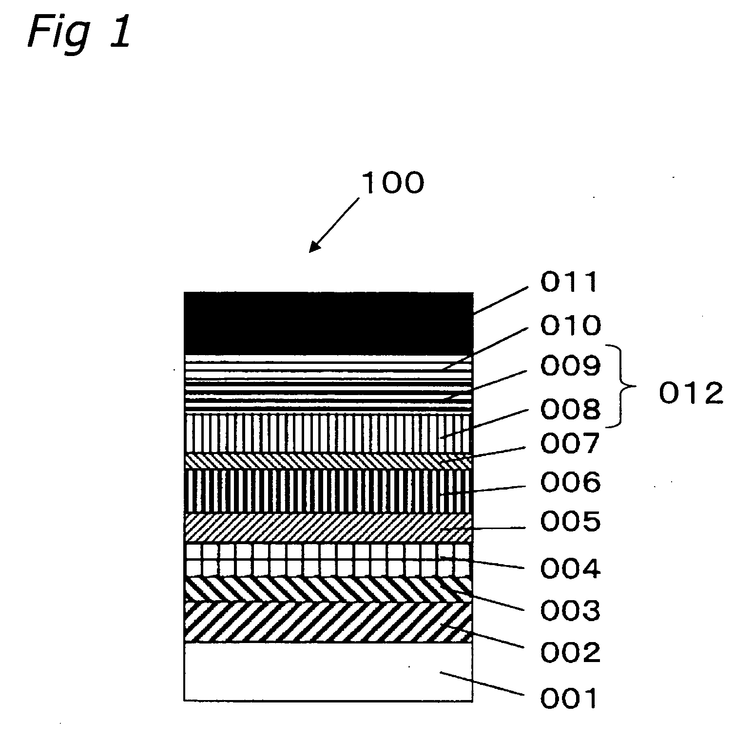
[0063]The main structure and method of manufacturing for recording medium 100 of the present Example are explained using FIG. 1.

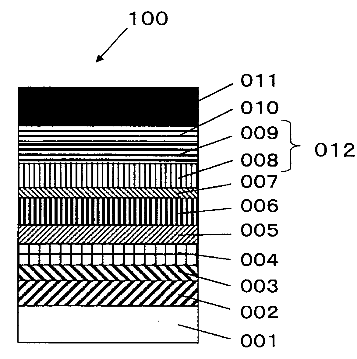
[0064]Recording medium 100 comprises above substrate 001 in sequence reflective layer 102, light-absorbing layer 003, reflected light side protective layer 004, reflected light side diffusion barrier layer 005, recording layer 006, incident light side diffusion barrier layer 007, incident light side protective layer 012 (first material layer 008 and second material layer 009), resin layer 010, and transparent substrate 011.

[0065]Substrate 001 had a thickness of 0.6 mm and used a disk-shaped polycarbonate resin substrate with a diameter of 120 mm.

[0066]Reflective layer 002 was formed as a 160 nm film using an Ag98Pd1Cu1 (atom %) alloy target.

[0067]Light-absorbing layer 003 was formed as a 30 mm film using an Si66Cr34 (atom %) alloy target.

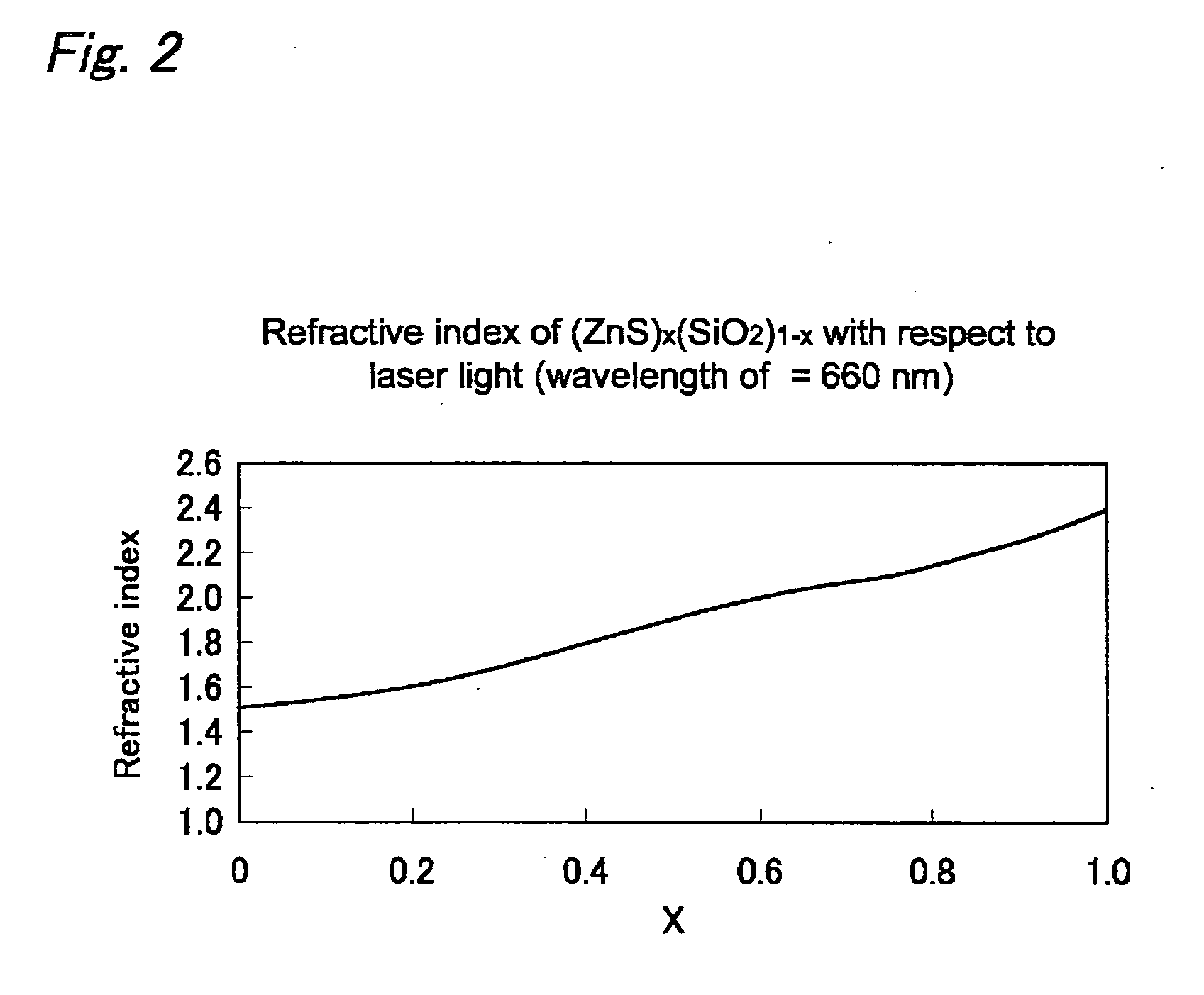
[0068]Reflected light side protective layer 004 used a mixture of 20 mol % of SiO2 in ZnS as the target, and when the rec...


PUM

PropertyMeasurementUnit
thicknessaaaaaaaaaa
thicknessaaaaaaaaaa
thicknessaaaaaaaaaa

Abstract

An optical information recording medium with favorable recording / reproducing characteristics and corrosion resistance is offered. To this end, the optical information recording medium of the present invention comprises in this sequence at least substrate 001 that has a guide groove, reflective layer 002, light-absorbing layer 003, reflected light side protective layer 004, recording layer 006 with optical properties that are transformed reversibly due to irradiation with laser light, incident light side protective layer 012 with a film thickness ≦50 nm, resin layer 010, and a transparent substrate 011 that is irradiated with laser light, where incident light side protective layer 012 includes a plurality of material layers, and among this plurality of material layers, a layer that constitutes an incident light side material layer 009 which is the most closest to the transparent substrate has minimum internal stress.

Description

TECHNICAL FIELD[0001]The present invention relates to an optical information recording medium on which it is possible to record / reproduce or overwrite information at high density using an optical means of laser light irradiation or the like, and a method for recording to an optical information recording medium.BACKGROUND ART[0002]Known media with which large quantities of information can be recorded and that can be overwritten and reproduced at high speed include magnetooptical recording media, phase change type recording media and the like. For these types of optical information recording media, differences in the optical properties of the recording materials that are produced by localized irradiation with laser light are utilized during recording / reproducing and rewriting. In the example of magnetooptical recording media, different rotational angles of the polarization plane of reflected light are utilized that are generated by different magnetization states. At the same time, for...

Claims


Application Information

Patent Timeline
Patent Type & Authority Applications(United States)
IPC IPC(8): G11B3/74G11B7/24G11B7/2403G11B7/24035G11B7/2405G11B7/24062G11B7/24067G11B7/243G11B7/2437G11B7/254G11B7/257G11B7/2578G11B7/258G11B7/2585G11B7/259
CPCG11B7/2403G11B7/24067G11B7/252G11B7/2578G11B7/259G11B2007/24312G11B2007/24314G11B2007/24316G11B2007/25706G11B2007/2571
Inventor KUSADA, HIDEOYAMADA, NOBORUHOSAKA, TOMIHARU
Owner PANASONIC CORP
Learn More