Corrosion-Resistant Steel Excellent in Toughness of Base Metal and Weld Portion, and Method of Manufacturing the Same

a technology of corrosion-resistant steel and applied in the field of corrosion-resistant steel, can solve the problems of poor toughness, reduced toughness of base metal, and considerable deformation of toughness, and achieve excellent toughness and large corrosion resistance

Inactive Publication Date: 2008-11-06
NIPPON STEEL CORP
View PDF1 Cites 2 Cited by
  • Summary
  • Abstract
  • Description
  • Claims
  • Application Information

AI Technical Summary

Benefits of technology

[0005]After considering the above-described situations, the present invention is aimed at providing a low-cost, corrosion-resistant steel showing a large corrosion resistance under various corrosive environments such as corrosive environment with dewing, aerial corrosive environment, corrosive environment with city water, and corrosive environment with seawater, and excellent in the toughness in the heat affected zone (HAZ).
[0006]Aiming at achieving the above-described objects, the present inventors made extensive studies from every aspect, in order to develop a steel showing excellent corrosion resistance under various corrosive environments such as corrosive environment with dewing, aerial corrosive environment, corrosive environment with city water, corrosive environment with concrete, and corrosive environment with seawater. First, after extensive investigations into techniques for improving the corrosion resistance under the above-described various environments, as well as the toughness of the weld portion, the present inventors found that a steel containing 3 to 11% of Cr, added with 0.1 to 2% of Al, showed a very excellent corrosion resistance under the above-described various corrosive environments. However, this sort of steel typically produces coarse ferrite when heated at 1200° C. or above during welding, due to its wide range of ferrite phase transformation, so that the toughness may degrade to a considerable degree, and may cause cracks and the like after welding. The present inventors then further went through a series of experiments, and found out that a mode of generation of the coarse ferrite phase transformation during welding can be estimated based on a parameter Tp below, expressed using amounts of addition of alloying elements. The parameter Tp can be expressed using concentrations of ferrite-forming elements (Cr, Al) and austenite-forming elements (Mn, Ni, for example) which suppress production of ferrite phase. The present inventors found out that production of ferrite at higher temperatures can be suppressed, when the parameter Tp has a value of not smaller than a predetermined level.
[0007]On the other hand, addition of some austenite-forming elements described in the above can suppress production of the coarse ferrite phase in the weld portion, but addition of large amounts of the alloying elements may promote formation of a low-temperature-transformation-forming phase with poor toughness in the process of cooling after rolling of the base metal, and thereby tends to lower the toughness of the base metal. The present inventors then made extensive studies on preventing such embrittlement, defined a parameter Tc which specifies concentrations of the alloying elements capable of ensuring a desirable level of toughness of the base metal after rolling, and found out that a desirable level of toughness can be ensured when the parameter Tc has a value of not smaller than a predetermined level.

Problems solved by technology

However, this sort of steel typically produces coarse ferrite when heated at 1200° C. or above during welding, due to its wide range of ferrite phase transformation, so that the toughness may degrade to a considerable degree, and may cause cracks and the like after welding.
On the other hand, addition of some austenite-forming elements described in the above can suppress production of the coarse ferrite phase in the weld portion, but addition of large amounts of the alloying elements may promote formation of a low-temperature-transformation-forming phase with poor toughness in the process of cooling after rolling of the base metal, and thereby tends to lower the toughness of the base metal.

Method used


Image

  • Corrosion-Resistant Steel Excellent in Toughness of Base Metal and Weld Portion, and Method of Manufacturing the Same
  • Corrosion-Resistant Steel Excellent in Toughness of Base Metal and Weld Portion, and Method of Manufacturing the Same
  • Corrosion-Resistant Steel Excellent in Toughness of Base Metal and Weld Portion, and Method of Manufacturing the Same

Examples


examples

[0080]Each of steels having compositions listed in Table 1 was melted and cast, hot rolled to give a 15-mm-thick steel plate, wherein some of them were further tempered, and subjected to the tests described below.

(1) Toughness Evaluation Test for Heat Affected Zone (HAZ)

[0081]All test pieces were collected from the center-thickness portion of the plate in the longitudinal direction.

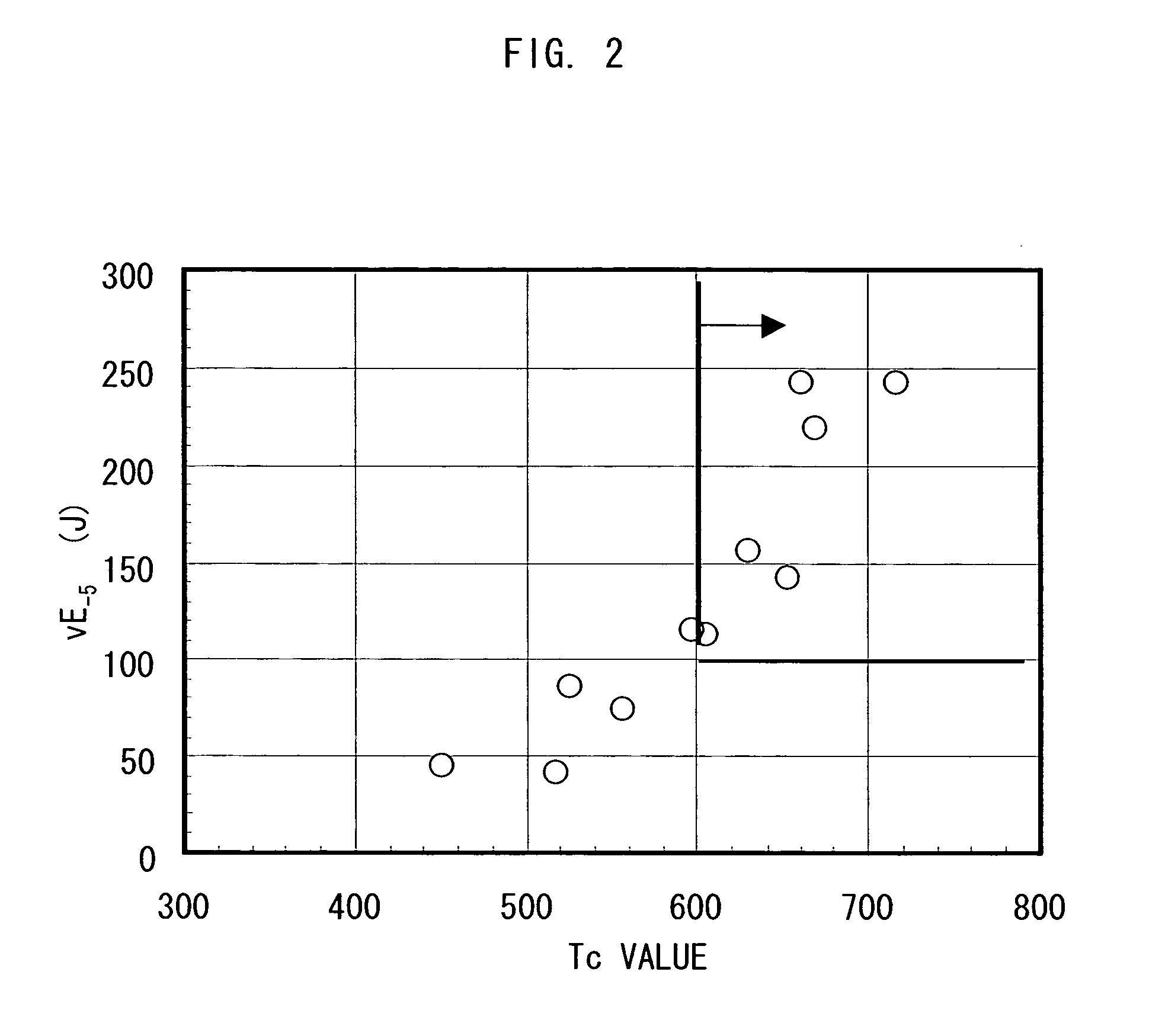
[0082]Evaluation of Toughness of Base Metal: Evaluation was carried out based on absorbed energy observed in the Charpy test at −5° C.

[0083]Evaluation of Toughness of Heat Affected Zone (HAZ): Impact test of the heat affected zone (HAZ) after being subjected to the welding heat cycles was carried out. The maximum heating temperature and the cooling rate in the test were set to 1400° C. and 15° C. / s, respectively. The base metal was also subjected to the impact test. Transition temperatures were determined for the both, and ΔvTrs=([transition temperature of base metal]−[transition temperature after heat cy...


PUM

PropertyMeasurementUnit
corrosionaaaaaaaaaa
toughnessaaaaaaaaaa
Tcaaaaaaaaaa

Abstract

A corrosion-resistant steel excellent in toughness of a base metal and a weld portion said steel slab contains, in % by weight, C: 0.2% or less; Si: 0.01 to 2.0%; Mn: 0.1 to 4% or less; P: 0.03% or less; S: 0.01% or less; Cr: 3 to 11%; Al: 0.1 to 2%; and N: 0.02%, and has values of 1150 or above, and 600 or above respectively for Tp and Tc expressed by the equations below using concentrations of Cr, Al, C, Mn, Cu and Ni respectively given as % Cr, % Al, % C, % Mn, % Cu and % Ni. Tp=1601−(34% Cr+287% Al)+(500% C+33% Mn+60% Cu+107% Ni); and Tc=910+80% Al−(300% C+80% Mn+15% Cr+55% Ni).

Description

TECHNICAL FIELD[0001]The present invention relates to a corrosion-resistant steel excellent in toughness of a base metal and a weld portion, and a method of manufacturing the same, and more specifically, a corrosion-resistant steel used in various forms under various corrosive environments, such as various containers, vacuum vessels, low-temperature heat exchangers and bathroom components used under corrosive environment with dewing or under indoor environment; such as bridge, support columns, tunnel reinforcing components, interior and exterior materials for buildings, roof materials and fittings used under aerial corrosive environment; such as various reinforcing structures and support columns used under corrosive environment with concrete; and such as marine vessels, bridges, piles, sheet piles and marine structures used under corrosive environments with seawater.BACKGROUND ART[0002]Steels used under various corrosive environments, such as high-temperature and high-humidity corro...

Claims


Application Information

Patent Timeline
Patent Type & Authority Applications(United States)
IPC IPC(8): C22C38/58C22C38/20C22C38/22C22C38/34C22C38/38C21D6/00C21D8/02C21D1/00C22C38/40C22C38/42C22C38/44C22C38/00
CPCC21D8/0205C22C38/02C22C38/06C22C38/38C22C38/58
Inventor SAITOH, NAOKIKATOH, KENJI
Owner NIPPON STEEL CORP
Why Eureka
Try Eureka