
Retractable safety barrier

a safety barrier and retractable technology, applied in the direction of sliding grilles, ways, buildings, etc., can solve the problems of door strength being insufficient to withstand impact, safety problems, and insufficient strength of barriers for industrial applications

Active Publication Date: 2005-09-29
RITE HITE HLDG CORP
View PDF59 Cites 36 Cited by
  • Summary
  • Abstract
  • Description
  • Claims
  • Application Information

AI Technical Summary

Benefits of technology

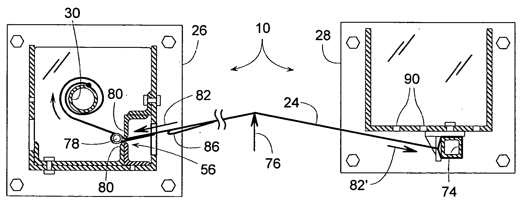
[0011] In some embodiments, a retractable rollup barrier is provided with substantial impact resistance by having the reactive force of the impact transfer directly between the barrier's retractable panel and its vertical support members without having to rely on the strength of the panel's take-up roller or the strength of the roller's anti-rotation mechanism.
[0017] In some embodiments, a retractable panel includes reinforcing straps that greatly increase the panel's strength.
[0020] In some embodiments, the rollup panel does not reach its full extension from within its housing until the panel experiences an impact. This feature allows a distal end of the panel to be readily hooked or unhooked from an anchored support member without the panel having to be pulled tightly against a hard stop to do so.
[0022] In some embodiments, two anchor support members of a retractable barrier can serve as bollard-like members for protecting the lateral edges of a door from damage.
[0023] In some embodiments, a distal end of a retractable panel can retract and stow within a pocket of a support member housing to protect the distal end from damage and avoid interfering with traffic when the retractable barrier is not in use.

Problems solved by technology

This may work well for light duty applications involving children and pets; however, such barriers do not appear adequate for industrial applications.
A permanent guardrail may prevent a forklift from striking the machine, but the guardrail may also interfere with material handling equipment trying to load and unload the machine of its work pieces.
Although a door typically exists at the edge of the platform, the door's strength may be insufficient to withstand the impact of a forklift, or the door may be left open for various reasons.
With the door open, however, the loading dock platform may create a safety problem.
Although costly massive safety gates have been used at loading docks, they can take up a lot of space even when they are opened to allow passage through the doorway.
Even though they may be able to stop a slowly moving forklift, an impact can cause considerable damage to the gate due to the gate's limited ability to resiliently absorb the impact.
Also, permanent or other conventional guarding may not be suitable for loading dock areas, as such guarding may interfere with operating the door, loading and unloading trucks, and operating a dock leveler that may be installed at the platform.
Unfortunately, a conventional barrier or guardrail extending over the dock leveler may restrict the deck's upward pivotal motion.
Since a dock leveler and the adjacent door move in the area where guarding may be needed, it becomes challenging to provide the area with a barrier that is movable yet sufficiently strong to impede heavy material handling equipment.

Method used


Image

  • Retractable safety barrier
  • Retractable safety barrier
  • Retractable safety barrier

Examples


Embodiment Construction

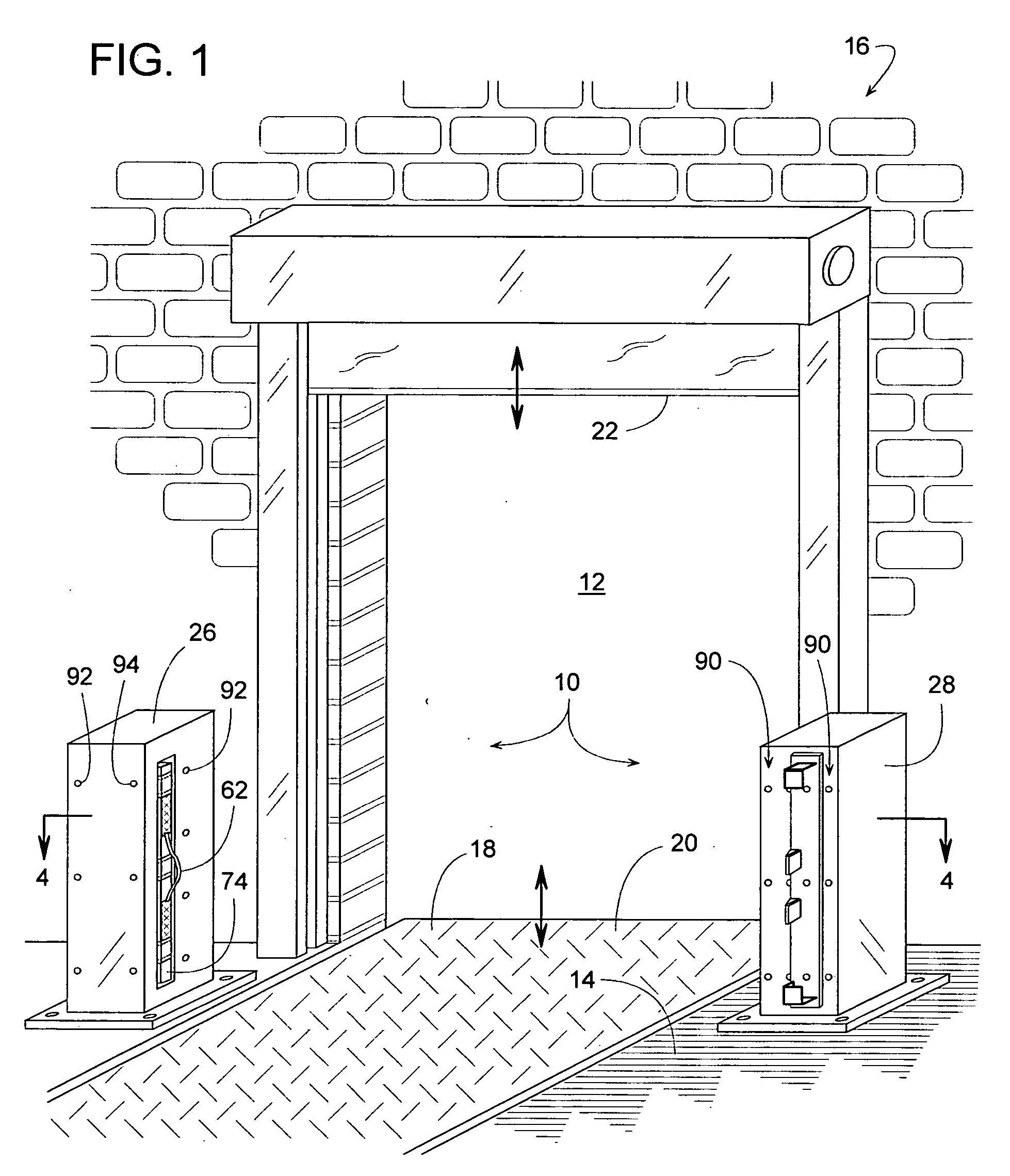
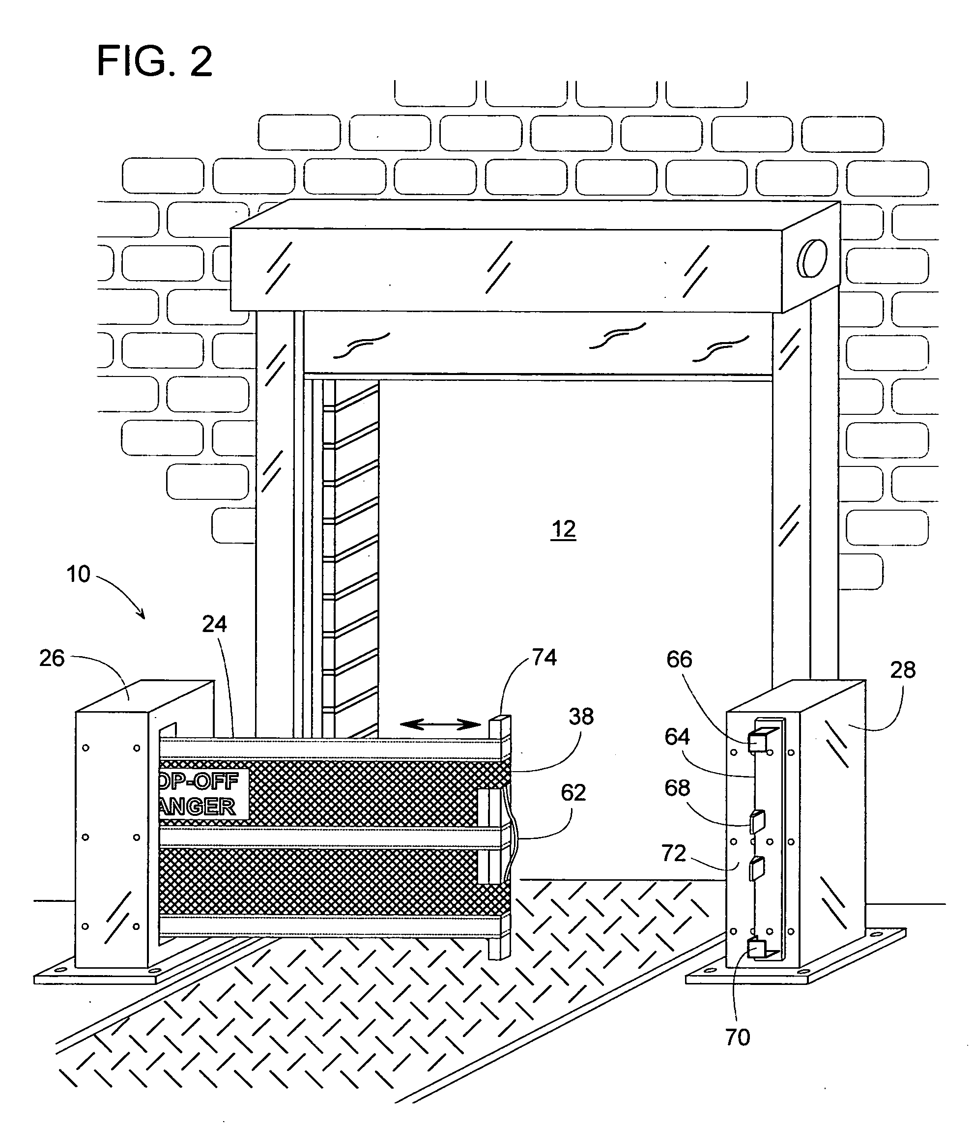
[0032] A retractable safety barrier 10 primarily intended for heavy duty industrial use is shown in FIGS. 1-3. The drawing figures show a view from within a building looking out through an open doorway 12. FIG. 1 shows barrier 10 in an open stored position, FIG. 3 shows barrier 10 in a blocking position, and FIG. 2 shows barrier 10 partway between its open and blocking positions.

[0033] Although barrier 10 is particularly suited for installation on an elevated platform 14 of a loading dock 16, barrier 10 can be readily applied to a broad range of heavy and light duty applications including, but not limited to, guarding machinery, guarding construction sites, restricting vehicular and pedestrian traffic, restraining cargo, restraining stock stored on high pallet racks, etc. Since the structure and function of various embodiments of barrier 10 may be similar regardless of the barrier's specific application, barrier 10 will be described with reference to its installation at loading doc...


PUM


Abstract

A retractable barrier includes a rollup or otherwise retractable panel that can extend between two spaced apart support members. When not in use, the panel can retract onto one of the support members to permit passage. The barrier provides substantial impact resistance by having the reactive force of the impact transfer directly between the barrier's retractable panel and its support members without having to rely on the strength of the panel's take-up roller or the strength of the roller's anti-rotation mechanism. This can be accomplished by having a slot-engaging stop member mounted directly to the panel itself. The stop member is preferably a pipe, rod, bar or some other vertically elongate member that can broadly distribute an impact reactive force over the height of the panel. In some embodiments, the barrier can be set for various doorway widths by simply repositioning the stop member's location on the retractable panel.

Description

BACKGROUND OF THE INVENTION [0001] 1. Field of the Invention [0002] The subject invention generally pertains to retractable safety barriers and more specifically to a heavy-duty barrier whose design features make it particularly suitable for impeding heaving loads such as, for example, a forklift at a loading dock platform. [0003] 2. Description of Related Art [0004] Many retractable safety barriers for doorways have been developed to help prevent children and pets from entering certain areas. To selectively open or block a doorway, some barriers include a rollup panel that can be unrolled to extend across and block the doorway. When not in use or to allow passage, the panel can wrap about a roller for storage along one side of the doorway. A few examples of retractable barriers with rollup panels are disclosed in U.S. Pat. Nos. 5,636,679; 5,690,317; 6,536,502; 5,505,244; and 6,056,038. [0005] Once such a rollup panel is extended across a doorway, usually some type of locking mechan...

Claims


Application Information

Patent Timeline
IPC IPC(8): E01F13/02E06B9/08
CPCE01F13/028
Inventor SNYDER, RONALD P.MILLER, JASON D.GRANT, DONALD P.MALY, PAUL J.GALLENBERGER, MIKE
Owner RITE HITE HLDG CORP
Learn More