
Battery pack manufacturing method, and battery pack

a battery pack and manufacturing method technology, applied in secondary cells, electrochemical generators, cell components, etc., can solve the problems of battery voltage difference, battery voltage difference, battery voltage difference, etc., and achieve the effect of suppressing the temporal increase of battery voltage differen

Active Publication Date: 2010-02-25
PANASONIC EV ENERGY CO LTD
View PDF4 Cites 38 Cited by
  • Summary
  • Abstract
  • Description
  • Claims
  • Application Information

AI Technical Summary

Benefits of technology

[0012]Meanwhile, secondary batteries such as used secondary batteries tend to gradually increase in internal resistance as they are used. The used secondary battery has a larger internal resistance value has a tendency that a temporal increase in battery voltage during charging is more largely and a temporal decrease in battery voltage during discharging is more greatly. Especially, such tendency is higher in a low temperature environment (e.g., a below-freezing temperature environment) and during high input / output (during charging / discharging at large current).
[0015]On the other hand, according to the manufacturing method of the invention, the internal resistance values of the used secondary batteries are respectively acquired, and then, in the selecting step, a plurality of used secondary batteries having internal resistance values close to each other are selected from the group of the used secondary batteries whose internal resistance values have been acquired. Subsequently, the selected used secondary batteries are combined with each other to constitute the battery pack. As above, such a combination of the used secondary batteries having the internal resistance values close to each other can prevent the temporal increase in battery voltage difference between the used secondary batteries constituting the battery pack during charging / discharging (especially, during charging / discharging in the low temperature environment). When the subject battery pack is combined with the battery controller and subjected to charging / discharging, it is possible to suppress the battery voltage or the characteristic value (a charge amount, etc.) resulting therefrom from being determined to be abnormal due to the temporal increase in battery voltage difference between the used secondary batteries constituting the battery pack. The subject battery pack can therefore be used appropriately.
[0018]According to the manufacturing method of the invention, on the other hand, the battery pack is constituted of the used secondary batteries having internal resistance values close to each other as mentioned above. This makes it possible to prevent one or more (the used secondary battery(s) having the large internal resistance value(s)) of the used secondary batteries constituting the battery pack from temporarily decreasing below the lower limit voltage value during charging / discharging as described above. It is therefore possible to prevent a disadvantage that one or more (the used secondary battery(s) having the large internal resistance value(s)) of the used secondary batteries constituting the battery pack prematurely reaches the end of their life.
[0019]As mentioned above, the battery pack manufacturing method of the invention can manufacture the battery pack capable of preventing the disadvantage that one or more of the used secondary batteries constituting the battery pack prematurely reaches the end of their life and of suppressing a temporal increase in battery voltage difference between the used secondary batteries during the charging and discharging (especially, during charging and discharging in the low temperature environment).
[0024]In the manufacturing method of the invention, a maximum difference in internal resistance value of the used secondary batteries constituting the battery pack (representing a difference in internal resistance value between one secondary battery having a highest internal resistance value and another secondary battery having a lowest internal resistance value; the same applies to the following description) is set to be 20% or less of the internal resistance value of the secondary battery having the minimum internal resistance value. Such combination of the used secondary batteries with the small difference in internal resistance value can prevent a disadvantage that one or more of the used secondary batteries constituting the battery pack prematurely reaches the end of its life. Furthermore, it is possible to suppress a temporal increase in battery voltage difference between the used secondary batteries during charging / discharging (especially, during charging / discharging in the low temperature environment).
[0027]In the battery pack of the invention, the used secondary batteries constituting the battery pack are combined so that the maximum difference in internal resistance value is 20% or less of the internal resistance value of the secondary battery having the minimum internal resistance value. This battery pack can prevent a disadvantage that one or more of the used secondary batteries constituting the battery pack prematurely reaches the end of its life due to irregularity in internal resistance value. Furthermore, it is possible to suppress a temporal increase in battery voltage difference between the used secondary batteries during charging / discharging (especially, during charging / discharging in the low temperature environment).

Problems solved by technology

However, in a battery pack used as the power source for electric vehicles or hybrid electric vehicles, one or more of the secondary batteries constituting the battery pack may be broken or reach the end of its life earlier than other batteries due to environments of use, characteristic difference among secondary batteries of the battery pack, or troubles of component parts of each secondary battery.
As a result, the intended performance of the battery pack may not be exhibited, which may cause the entire system failure.

Method used


Image

  • Battery pack manufacturing method, and battery pack
  • Battery pack manufacturing method, and battery pack
  • Battery pack manufacturing method, and battery pack

Examples


embodiment 1

[0044]A detailed description of a first embodiment of the present invention will now be given referring to the accompanying drawings.

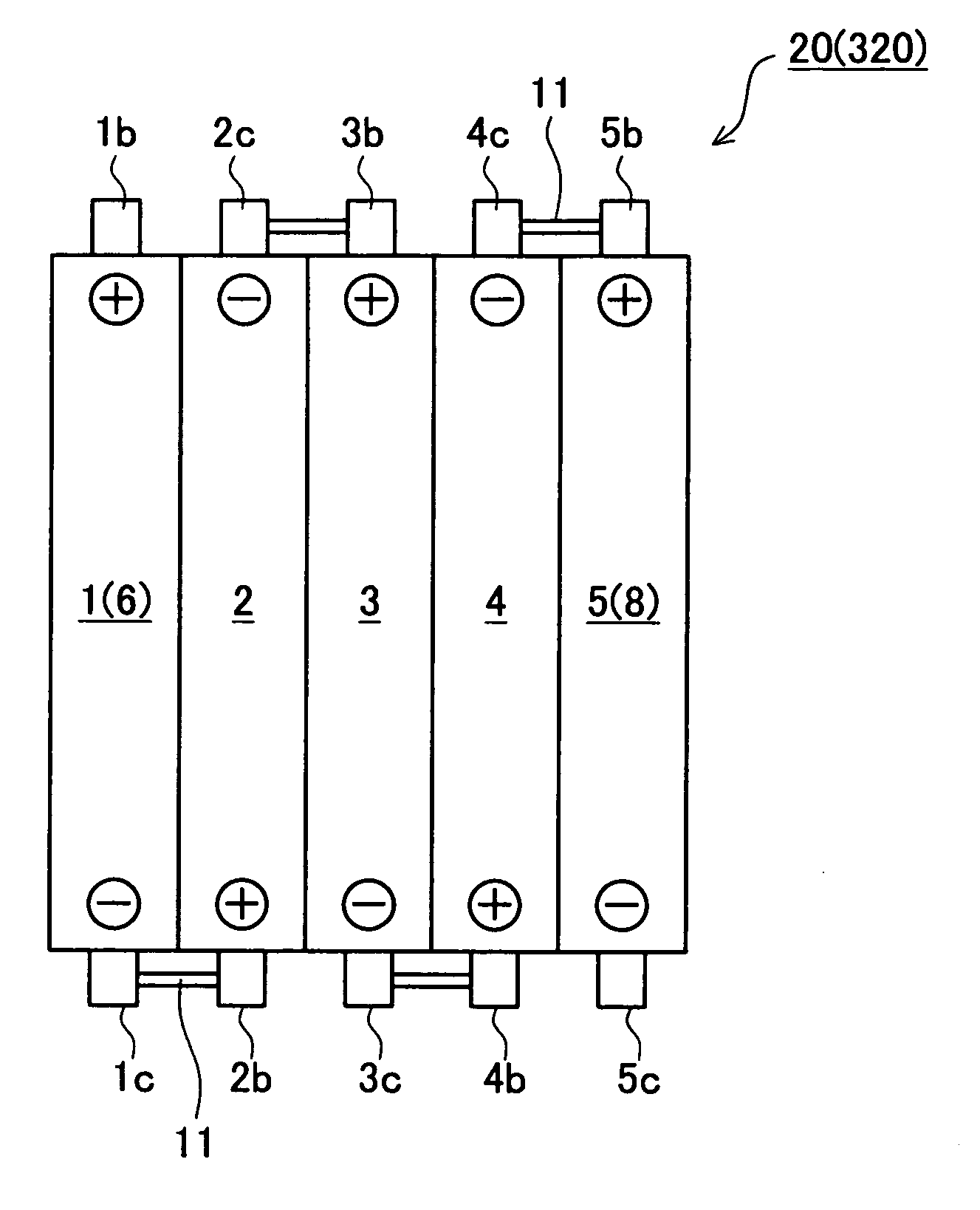
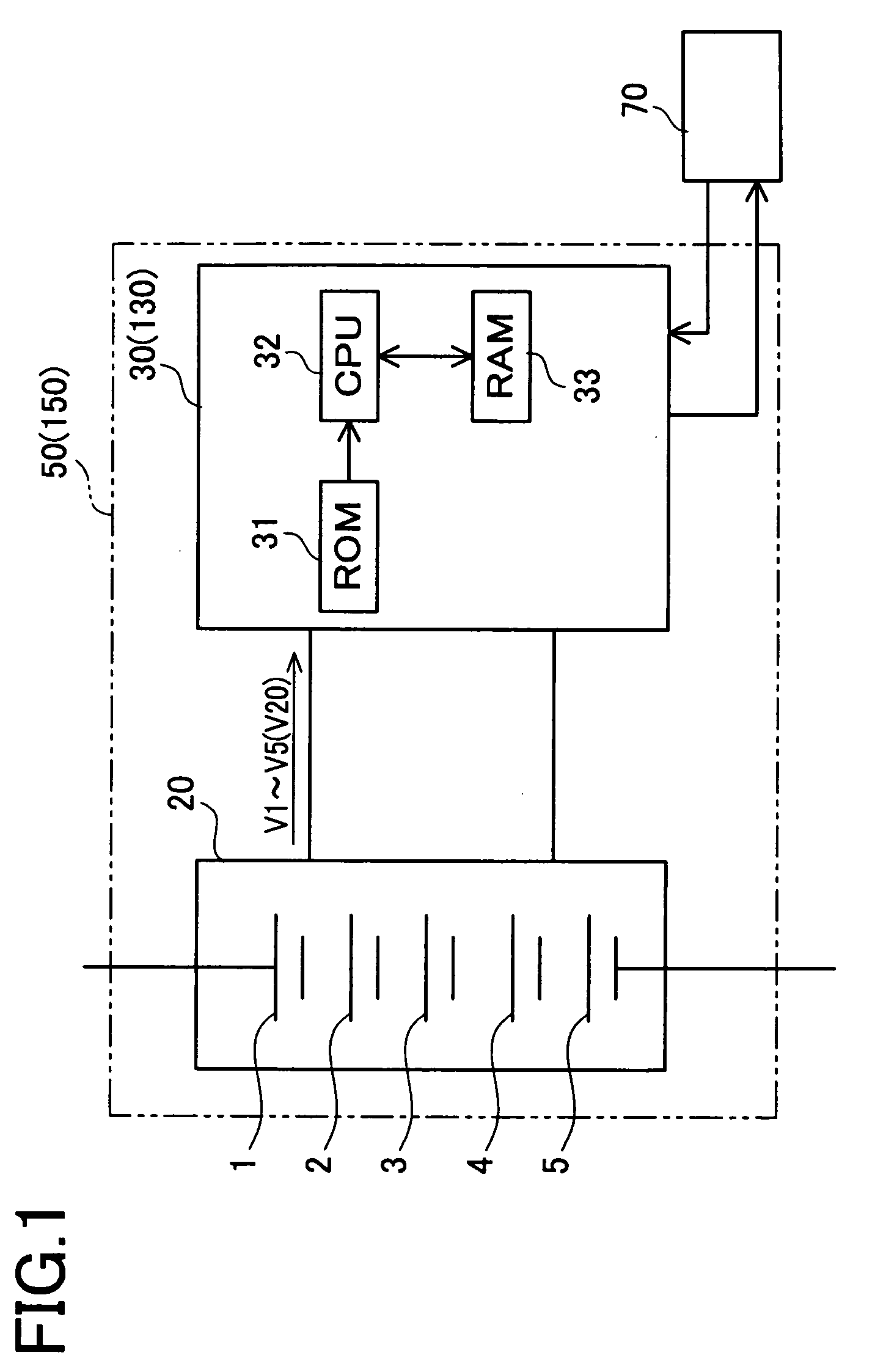
[0045]A battery pack (assembled battery) equipped with a controller 50 (hereinafter, a “controller-equipped battery pack 50”) in the first embodiment will be first explained below. The controller-equipped battery pack 50 includes a battery pack (an assembled battery) 20 and a battery controller 30 as shown in FIG. 1. As shown in FIG. 2, the battery pack 20 includes five used secondary batteries (used secondary batteries 1 to 5) arranged in a row and electrically connected in series by way of connecting members 11.

[0046]The battery controller 30 is a known battery controller (see, for example, JP2006-79961A), and includes a ROM 31, a CPU 32, a RAM 33, and others. As shown in FIG. 1, the battery controller 30 is configured to detect battery voltages V1 to V5 of used secondary batteries 1 to 5 constituting the battery pack 20. The battery controller 30 fu...

second embodiment

[0076]Next, a controller-equipped battery pack 150 in a second embodiment is explained below. The controller-equipped battery pack 150 in the second embodiment is identical to the controller-equipped battery pack 50 in the first embodiment excepting only a processing program (not shown) built in a battery controller.

[0077]Specifically, a battery controller 130 in the second embodiment detects every voltage of the used secondary batteries 1 to 5 (battery pack voltage V20) constituting the battery pack 20 as indicated in parentheses in FIG. 1. Furthermore, the battery controller 130 determines whether or not the detected battery pack voltage V20 is abnormal. To be concrete, if the battery pack voltage V20 is below a lower limit, for example, it is determined that the battery pack voltage is abnormal.

[0078]Meanwhile, if the used secondary batteries 1 to 8 are discharged until their battery voltages decrease below the lower limit voltage value (e.g., 1.0V), metal components or constitue...


PUM

PropertyMeasurementUnit
Fractionaaaaaaaaaa
Temperatureaaaaaaaaaa
Electrical resistanceaaaaaaaaaa

Abstract

Provided are a battery pack manufacturing method, which can prevent a drawback that some of used secondary batteries constituting a battery pack prematurely come to the end and which can suppress the enlargement of the temporary voltage difference between the used secondary battery at a charging / discharging time (especially in a low-temperature circumstance), and a battery pack. The battery pack manufacturing method comprises an acquiring step (Step S1) of acquiring the individual internal resistances of the secondary batteries already used, a selection step (Step S2) of selecting a plurality of the used secondary batteries having the internal resistances close to each other from a group of the used secondary batteries whose internal resistances have been acquired, and an assembling step (Step S3) of combining the used secondary batteries selected, to constitute the battery pack.

Description

TECHNICAL FIELD[0001]The present invention relates to a battery pack manufacturing method and a battery pack (an assembled battery).BACKGROUND ART[0002]Recently, various secondary batteries have been proposed as the power source for portable devices and mobile devices or as the power source for electric vehicles or hybrid electric vehicles. When the secondary batteries are to used as the power source for electric vehicles or hybrid electric vehicles, high output power is demanded and hence a plurality of secondary batteries are electrically connected in series to be used as a battery pack (an assembled battery).[0003]However, in a battery pack used as the power source for electric vehicles or hybrid electric vehicles, one or more of the secondary batteries constituting the battery pack may be broken or reach the end of its life earlier than other batteries due to environments of use, characteristic difference among secondary batteries of the battery pack, or troubles of component pa...

Claims


Application Information

Patent Timeline
IPC IPC(8): H01M10/00H01M50/209
CPCH01M2/10H01M10/42Y10T29/49108H01M10/48H01M10/4207Y02E60/10H01M50/209
Inventor OKUMURA, MOTOYOSHIMAEGAWA, KATSUNORI
Owner PANASONIC EV ENERGY CO LTD
Learn More