Self-attaching female fastener and method of installation

Inactive Publication Date: 2005-02-08
WHITESELL FORMED COMPONENTS
View PDF47 Cites 36 Cited by
  • Summary
  • Abstract
  • Description
  • Claims
  • Application Information

AI Technical Summary

Benefits of technology

The self-attaching female fastener element of this invention may be formed by conventional cold header techniques and may be utilized as a pierce nut and provides superior integrity in a fastener and panel assembly formed by the method of this invention including improved push-off strength and resistance to rotation in the panel or torque resistance. The self-attaching female fastener element of this invention includes an annular pilot portion having a bore extending through an annular end face of the pilot portion, an annular flange portion surrounding the pilot portion preferably having a planar annular bearing face generally parallel to and spaced below the plane of the end face of the pilot portion, an annular groove in the annular bearing face of the flange portion surrounding the pilot portion including an annular bottom wall, an inner side wall adjacent the pilot portion and an outer side wall inclined from the bottom wall toward the pilot portion defining a restricted or “re-entrant” opening of the annular groove adjacent the bearing face. In a preferred embodiment, the inner side wall of the annular groove is also inclined outwardly from the bottom wall of the groove toward the flange portion providing improved push-off strength.
The bottom wall of the groove of the self-attaching fastener element of this invention includes a plurality of circumferentially spaced radial protrusions projecting from the bottom wall of the groove which, in a preferred embodiment, are inclined radially from adjacent the inner side wall to the outer side wall of the annular groove. The radial protrusions, particularly when inclined radially outwardly, drive panel metal beneath the inclined outer side wall of the groove providing improved push-off strength and torque resistance. In a preferred embodiment, the radial protrusions project from the bottom wall of the groove and include side walls extending generally perpendicular to the bottom wall of the groove and panel metal is deformed around the radial protrusions against the side walls of the protrusions providing resistance to turning of the female fastener element in the panel. In a preferred embodiment, wherein the radial protrusions are inclined, the radial protrusions preferably extend from the inner side wall to the outer side wall of the annular groove, such that the side walls of the protrusions are triangular, providing the greatest torque resistance adjacent the outer side wall of the groove, thereby providing maximum torque resistance.
A preferred embodiment of the self-attaching female fastener of this invention further includes circumferentially spaced radial grooves in the outer side wall of the annular groove, preferably equally spaced between the radial protrusions of the bottom wall. In a preferred embodiment, the radial grooves in the outer side wall of the annular groove are channel-shaped having an outer wall extending from the annular bearing face of the flange portion to the bottom wall of the annular groove. In a preferred embodiment, the outer wall of the radial grooves is also inclined inwardly toward the pilot portion and parallel to the outer wall of the annular groove. In a preferred embodiment, the circumferential width of the outer wall of the radial groove is equal to or greater than twice the circumferential width of the radial protrusions projecting from the bottom wall of the annular groove. During installation of the self-attaching female fastener, panel metal is driven against the bottom wall of the annular groove and radially into the radial grooves, whereby the radial grooves provide both improved torque resistance and push-off strength, particularly in thin metal applications as used by the automotive and appliance industries. In another preferred embodiment, the outer wall of the pilot portion includes radial grooves which preferably extend into the end face of the pilot portion, but are spaced from the bottom wall of the annular groove which provides additional torque resistance, particularly in thicker panel metal applications.
The method of attaching a pierce nut of this invention includes driving the end face of the pilot portion against a metal panel, thereby piercing an opening through the metal panel and receiving the pilot portion through the opening in the panel. The method then includes driving an annular portion of the panel surrounding the opening against the annular bottom wall of the annular groove and against the inclined radial protrusions projecting from the bottom wall of the annular groove. The inclined radial protrusions then drive the annular portion of the panel radially beneath the inclined outer side wall of the annular groove, securely retaining the self-piercing nut on the panel and circumferentially around the inclined radial protrusions, preventing rotation of the pierce nut on the panel. In a preferred embodiment of the self-piercing nut of this invention which includes the radial grooves in the outer wall of the annular groove, the annular panel portion is deformed against the radial protrusions is also deformed radially into the radial grooves in the outer wall of the annular groove and preferably beneath the inclined portion of the outer wall of the radial grooves, providing improved push-off strength.

Problems solved by technology

However, rolling techniques used for manufacturing self-piercing nuts require a rolling mill, expensive equipment and know how.
A self-attaching nut, particularly a pierce nut, formed by conventional cold header techniques is less expensive to manufacture, but generally has less structural integrity in the joint, particularly including torque resistance or resistance to rotation of the nut in the panel after installation.
However, pierce nuts formed by the method disclosed in this patent when installed in a panel do not have sufficient structural integrity for many applications, particularly including relatively thin metal panels as used by the automotive and appliance industries.

Method used


Image

  • Self-attaching female fastener and method of installation
  • Self-attaching female fastener and method of installation
  • Self-attaching female fastener and method of installation

Examples


Embodiment Construction

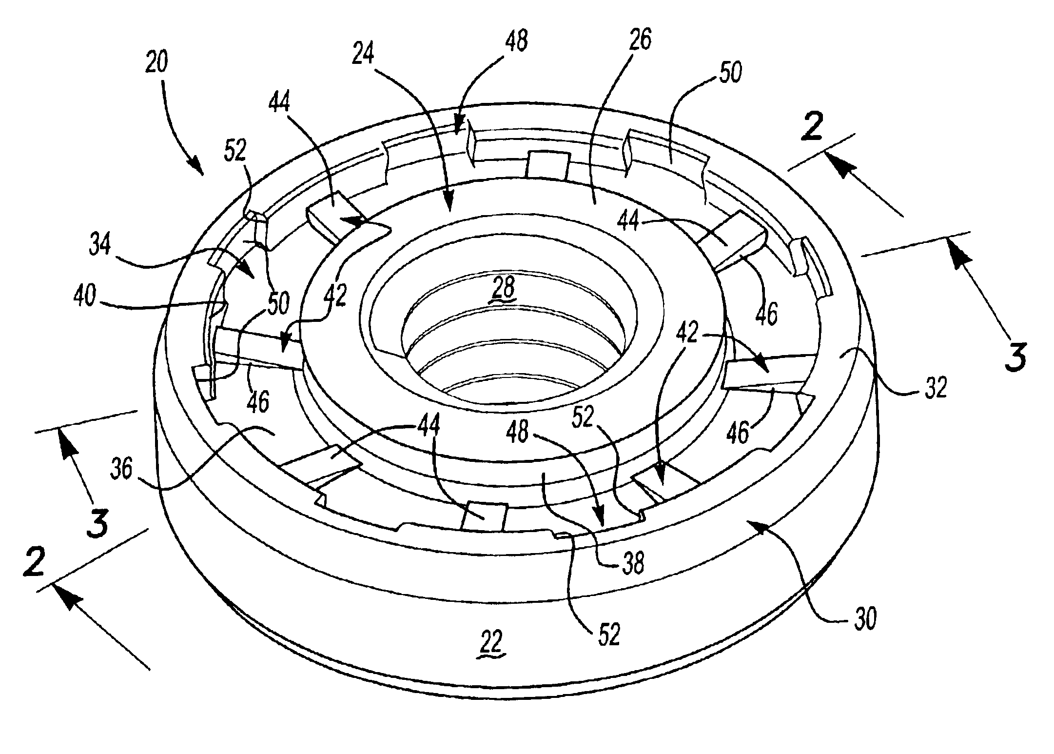
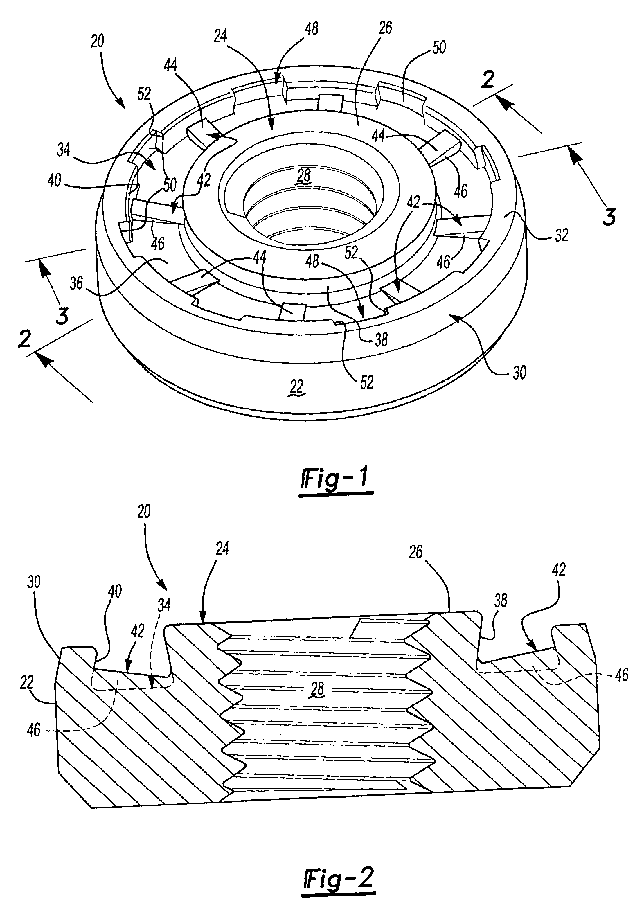
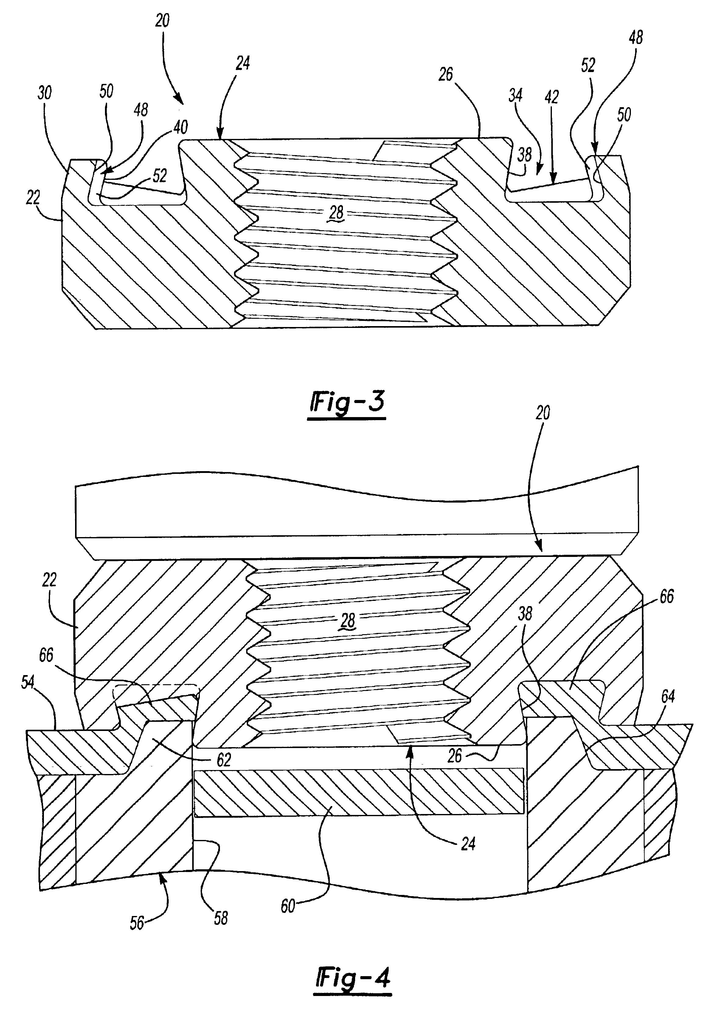
As set forth above, the self-attaching female fastener element of this invention may be utilized as a pierce nut, wherein the pierce nut has improved integrity when installed in a panel, and may be formed by conventional cold header techniques. As shown in FIGS. 1 to 3, the self-attaching nut 20 of this embodiment of the invention includes a generally cylindrical body portion 22, including an annular pilot portion 24 having a planar end face including a bore 28, which may be threaded as shown. Alternatively, the bore 28 may be unthreaded for receipt of a thread forming or thread rolling bolt or male fastener (not shown). The self-attaching nut 20 further includes an annular flange portion 30 surrounding the pilot portion 24 having a planar bearing face 32 parallel to, but spaced below the plane of the end face 26 of the pilot portion. An annular groove 34 is defined in the bearing face 32 having a bottom wall 36, an inner side wall 38 and an outer side wall 40. As best shown in FIGS...


PUM

PropertyMeasurementUnit
Widthaaaaaaaaaa

Abstract

A self-attaching nut having an annular pilot, an annular flange surrounding the pilot and an annular groove in the bearing surface surrounding the pilot, wherein the bottom wall of the groove has inclined rectangular protuberances and the outer wall of the groove has radial channel-shaped grooves spaced between the radial protuberances. During installation, panel metal is driven against the inclined radial protuberances, driving panel metal under the inclined outer wall of the groove and into the radial grooves in the flange.

Description

FIELD OF THE INVENTIONThe present invention relates to self-attaching female fastener elements, particularly including pierce nuts, which may be formed by conventional cold header techniques and which provide improved retention and resistance to rotation of the fastener on a panel following installation.BACKGROUND OF THE INVENTIONSelf-attaching female fasteners, including pierce nuts, generally include a central projecting pilot portion having a planar end face, a bore extending through the end face which may be threaded or unthreaded, flange portions on at least opposed sides of the pilot portion each having a planar bearing face spaced below the plane of the end face of the pilot portion, and grooves in the bearing face of the flange portion or in the sides of the pilot portion which receive the panel and retains the self-attaching female fastener element on the panel.Self-attaching female fastener elements of the type described above may be formed by either rolling a metal wire i...

Claims


Application Information

Patent Timeline
IPC IPC(8): B21K1/70B21K1/00B23P19/06F16B37/04F16B37/06B21D39/00
CPCB21K1/702F16B37/068B23P19/062
Inventor PARKER, JOHN M.BOGGS, KERRY V.
Owner WHITESELL FORMED COMPONENTS
Why Eureka
Try Eureka