
Card type wireless communication module

Inactive Publication Date: 2011-06-02
MITSUMI ELECTRIC CO LTD
View PDF4 Cites 11 Cited by
  • Summary
  • Abstract
  • Description
  • Claims
  • Application Information

AI Technical Summary

Benefits of technology

[0017]Accordingly, embodiments of the present invention may provide a novel and useful card type wireless communication module solving one or more of the problems discussed above.
[0018]More specifically, the embodiments of the present invention may provide a card type wireless communication module whereby degradation of transmission efficiency of a high frequency characteristic can be prevented and strength of the module can be improved.

Problems solved by technology

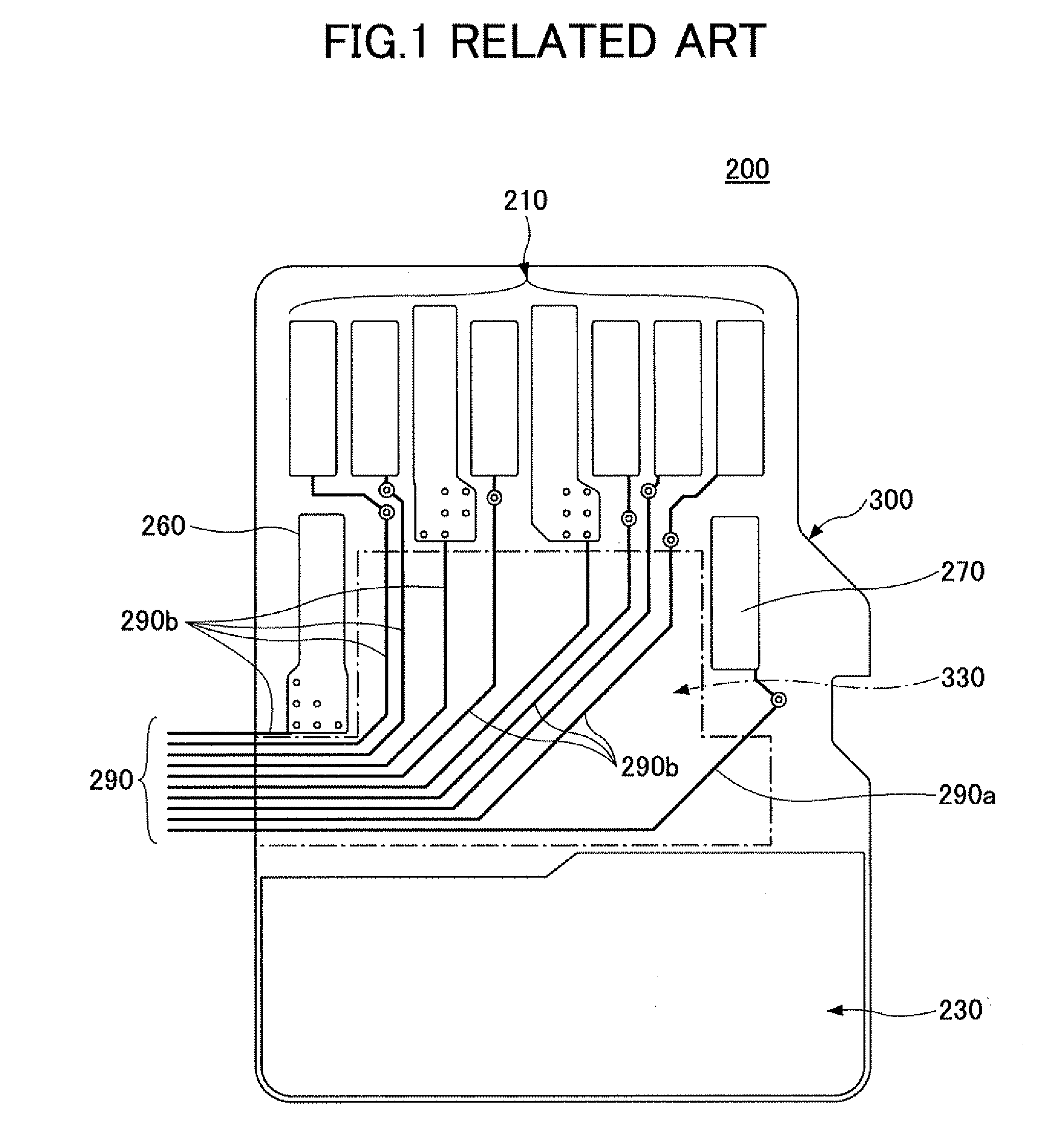
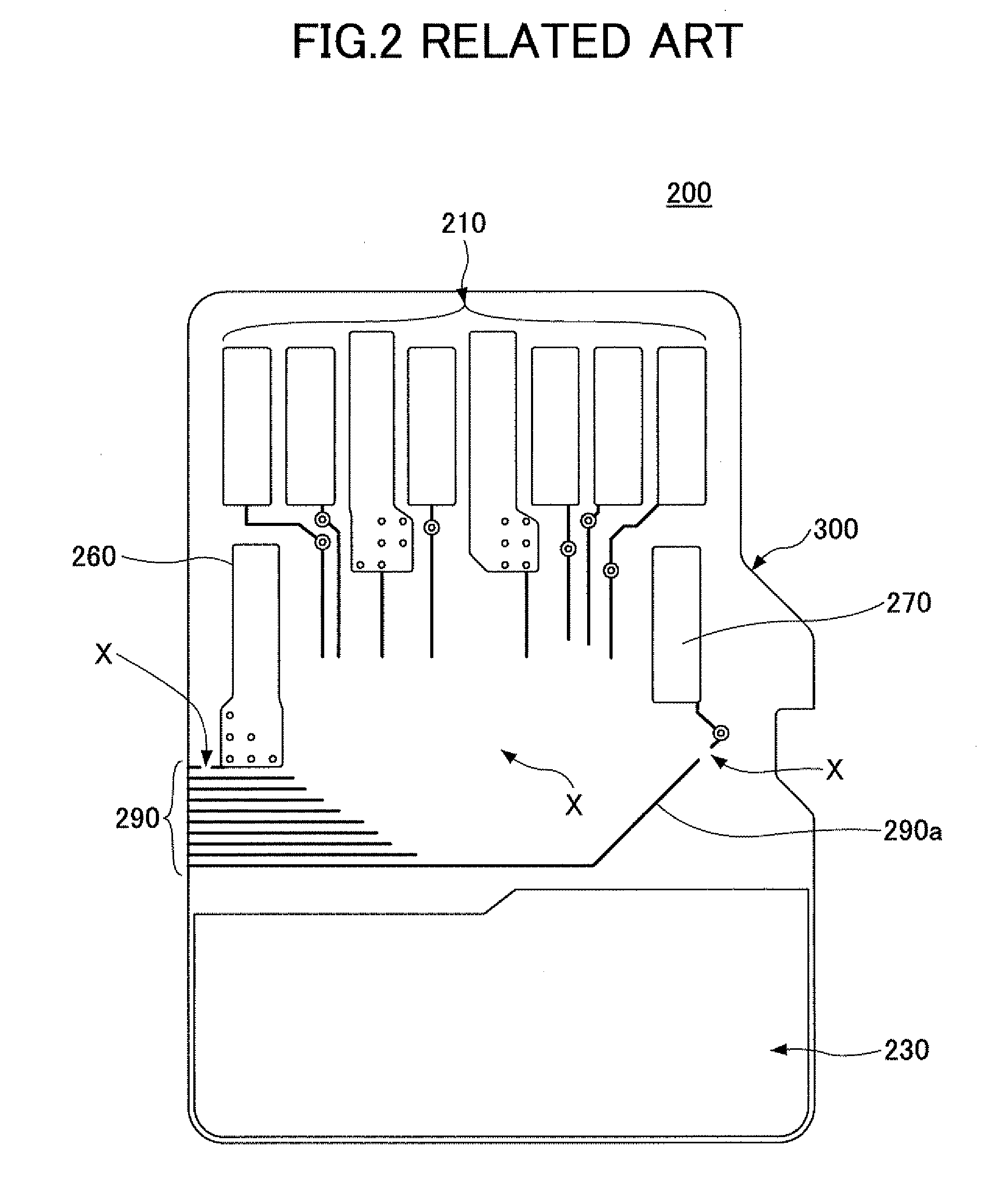
Therefore, if the remaining wiring pattern 290a is provided in parallel with the high frequency transmission line, mismatch of impedance may be generated on the transmission line.
Because of this, elements reacting at a high frequency may be increased so that transmission loss may be generated.
However, if an area of the feeding wiring pattern arrangement area 330 is wide, there is no freedom degree of design for the board 300 and therefore it may not be possible to form the reinforcing pattern.

Method used


Image

  • Card type wireless communication module
  • Card type wireless communication module
  • Card type wireless communication module

Examples


Embodiment Construction

[0033]A description is given below, with reference to the FIG. 3A through FIG. 11 of embodiments of the present invention.

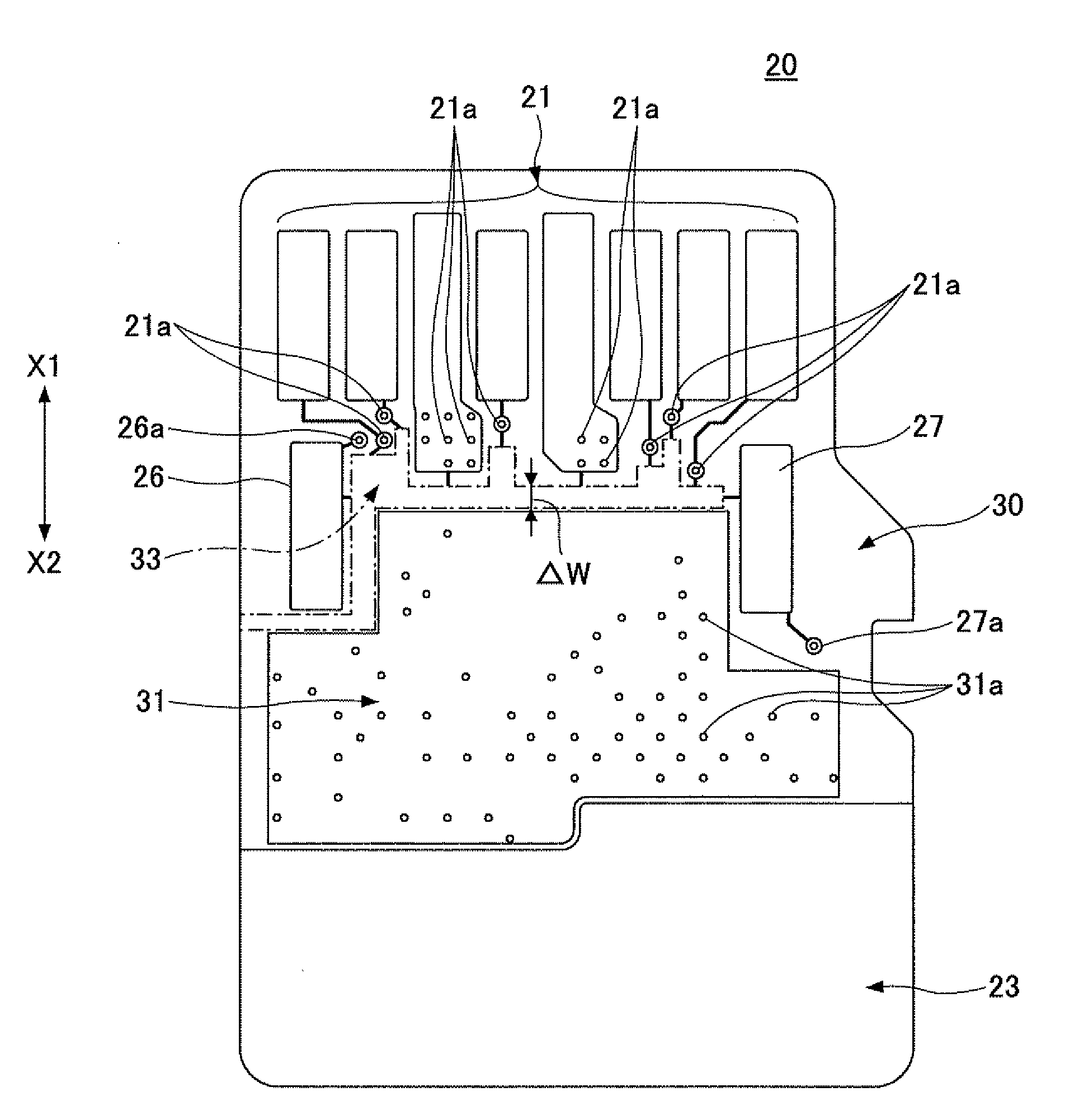
[0034]FIG. 3A is a plan view showing a mobile communication terminal 10 where a card type wireless communication module 20 of an embodiment of the present invention is provided. FIG. 3B is a plan view of the card type wireless communication module 20 of the embodiment of the present invention. A state where a rear surface cover of the mobile communication terminal 10 is taken off is illustrated in FIG. 3A.

[0035]In the mobile communication terminal 10, a card device connector 12 is provided in the vicinity of a battery receiving position where a battery pack 11 is received. The card type wireless communication module 20 is inserted in a direction indicated by an arrow in the card device connector 12. The card type wireless communication module 20 has a structure whereby the card type wireless communication module 20 can be attached to or detached from the mobile c...


PUM


Abstract

A card type wireless communication module, includes a board; a plurality of terminals formed on the board, the terminals including an external antenna terminal, the terminals having a plating process applied thereto; and a ground pattern formed on the board; wherein a feeding wiring pattern arrangement area is formed between forming positions of the terminals on the board and a forming position of the ground pattern, the feeding wiring pattern arrangement area has a feeding wiring pattern formed thereon, the feeding wiring pattern feeds power to the terminals at the time of an electrolytic plating process, and the feeding wiring pattern is removed after the electrolytic plating process is completed.

Description

CROSS-REFERENCE TO RELATED APPLICATIONS[0001]This patent application is based upon and claims the benefit of priority of Japanese Patent Application No. 2009-274982 filed on Dec. 2, 2009, the entire contents of which are incorporated herein by reference.BACKGROUND OF THE INVENTION[0002]1. Field of the Invention[0003]The present invention generally relates to card type wireless communication modules. More specifically, the present invention relates to a card type wireless communication module including a high frequency terminal where a plating process is applied.[0004]2. Description of the Related Art[0005]In a mobile communication terminal such as a portable phone, it is generalized that the terminal has a wireless function such as infrared or Bluetooth (registered trademark) transmitting and receiving for transferring data a short distance. In addition, it has been demanded that a function of a wireless LAN for transferring data an intermediate distance be additionally provided in ...

Claims


Application Information

Patent Timeline
IPC IPC(8): H01Q1/50H05K1/00H04B1/38H05K1/02
CPCG06K19/07743G06K19/07769G06K19/07749
Inventor ARIMURA, SHOGO
Owner MITSUMI ELECTRIC CO LTD
Learn More